Check valve

a check valve and valve body technology, applied in valve housings, machines/engines, liquid fuel engines, etc., can solve the problems of premature failure, exposing seating surfaces, and prior art check valve failure, and achieve the effect of more reliable check

Active Publication Date: 2016-05-31
ROYS CURTIS
View PDF76 Cites 7 Cited by
  • Summary
  • Abstract
  • Description
  • Claims
  • Application Information

AI Technical Summary

Benefits of technology

[0006]A check valve includes an internal fluid trap that prevents gas from the output path from passing through the check valve and degrading the sealing surfaces. When used with a natural gas compressor lubrication system, the internal fluid trap prevents hot gases and debris from the compressor interior from degrading the sealing surface within the check valve. Some embodiments include more than one fluid reservoir.

Problems solved by technology

Prior art check valves fail due to hot gas and debris entering the check valve each time the pump causes it to open to allow lubricant to be injected into the compressor cylinder or rod packing gland.
This exposes the seating surfaces to the hot gas and debris that are in the gas stream of the compressor.
The hot gas heats the sealing surfaces in the check valve causing it to fail prematurely.
The debris in the gas stream migrates into the check valve and causes the balls to stick open.
As the debris lodges between the sealing surface and the ball, the hot gas migrates upstream into the lubricant tubing and causes problems with the pistons that inject oil into the cylinder or rod packing gland.
This adds extra cost to the components and adds another lubricant leak path to the system.
Another disadvantage of current check valve protectors is the positioning of the lubricant inlet.
Another problem with prior art check valve protectors is they incorporate a single NPT thread on the outlet.
This causes installation issues when installing the device.
This causes extreme stress on the threads in the compressor cylinder and has been known to destroy both the cylinder threads and the threads on the device.
The over torqueing of the threads deforms the metal and not only causes issues with leaking explosive gases to the atmosphere, but also eliminates the ability to reuse that particular injection point if a new device has to be installed.
When this occurs the compressor cylinder must be removed and sent to a machine shop to be repaired or a new cylinder must be installed, which costs the owner / operator thousands of dollars.

Method used


Image

  • Check valve
  • Check valve
  • Check valve

Examples


Embodiment Construction

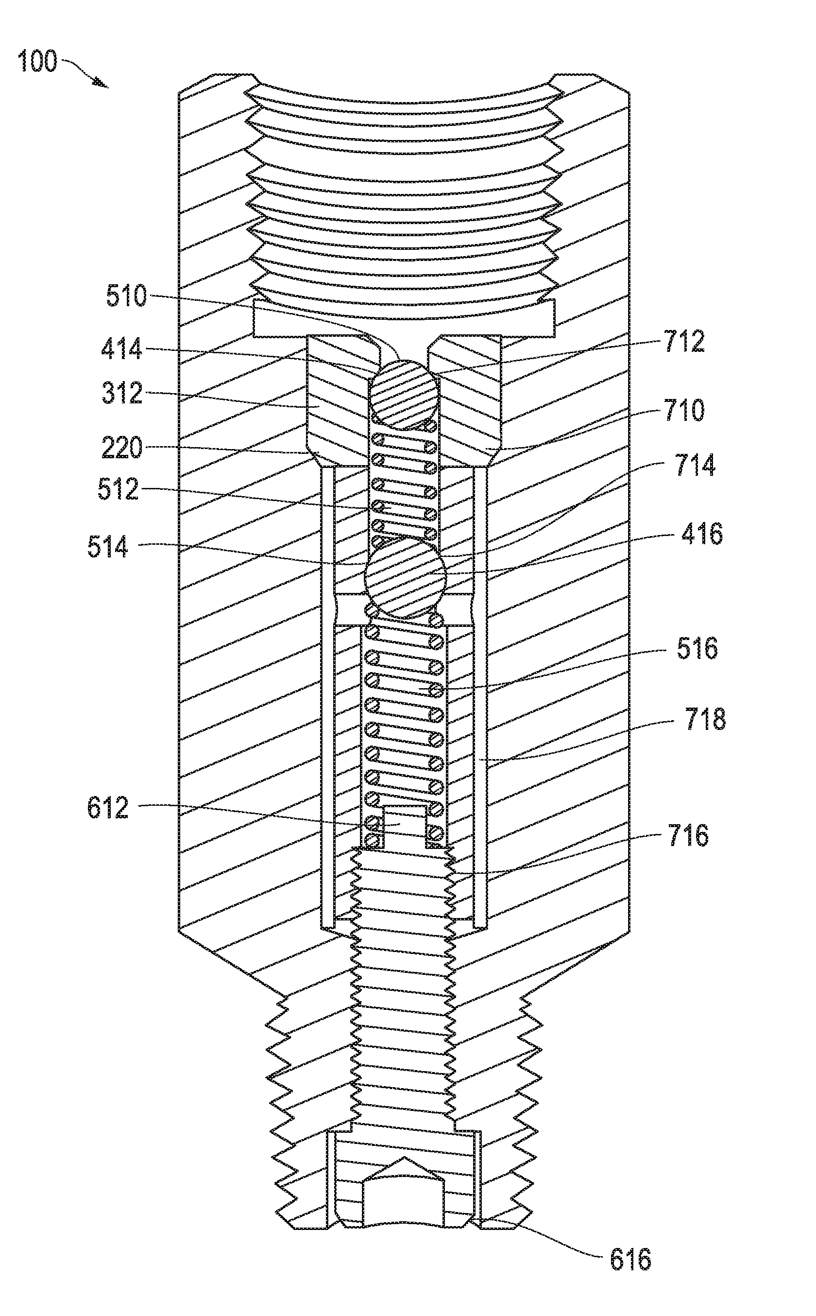
[0018]A preferred check valve includes an internal liquid trap between the sealing components and the outlet to prevent backflow from the outlet from deteriorating the sealing components. In a natural compressor lubrication system, a preferred check valve includes an internal oil trap between the sealing components and the outlet to prevent backflow of hot gases and debris from the compressor. In the description below, the terms “top” and “bottom” are used in relation to the figures.

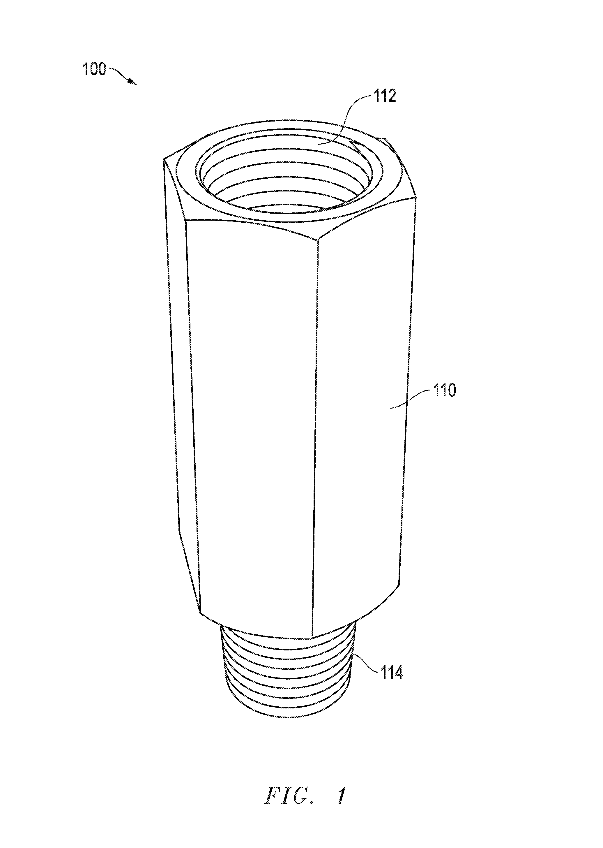
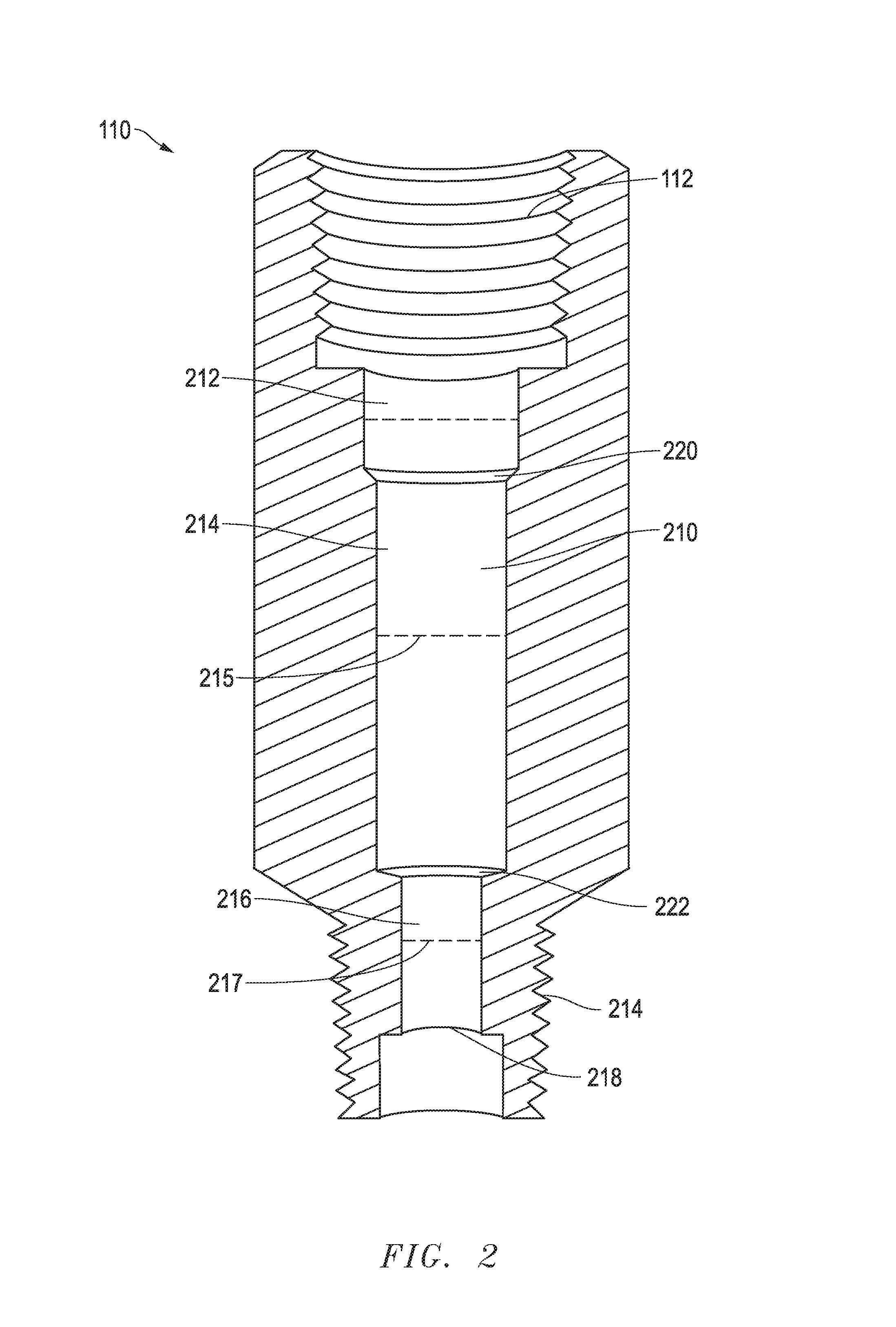
[0019]Referring now to FIG. 1, a perspective view of a check valve is shown according to an illustrative embodiment. Check valve 100 comprises valve body 110. Valve body 110 can be constructed from a solid piece of metal, such as stainless steel. The material chosen will depend on the application, but for use in a natural gas compressor lubrication system, the material should be resistant to corrosion by the gases and debris in the compressor.

[0020]A cavity 112 having female pipe threads is formed at a f...


PUM


Abstract

A check valve includes an internal liquid trap that prevents the backflow of gas and debris from degrading the valve. The internal liquid trap can be formed by internal passages within a valve housing. One embodiment includes a plurality of concentric fluid passages, connected by a set of radial conduits.

Description

TECHNICAL FIELD OF THE INVENTION[0001]The present invention relates to extending the life of check valves in hostile environments, and is particularly suitable for use in lubrication systems for natural gas compressors.BACKGROUND OF THE INVENTION[0002]Natural gas compressors require a consistent supply of lubricant. To enter the compressor, the lubricant must be delivered at a pressure that is greater than the pressure within the compressor. Lubricant is typically distributed to the lubrication points by a divider block, which periodically delivers a small amount of lubricant at a high pressure to each lubrication point. A check valve is used to prevent hot gases from the compressor cylinder from flowing into the lubrication system when the pressure from the lubrication system is reduced, such as between cycles of the divider block. When the lubricant pressure is sufficiently high, the check valve opens and lubricant is injected into the compressor cylinder. When the lubricant press...

Claims


Application Information

Patent Timeline
Patent Type & Authority Patents(United States)
IPC IPC(8): F16K15/00F04B53/10F16K15/04F16K17/20F16N21/00
CPCF04B53/1002F16K15/042F16K15/044F16K17/20F16N21/00Y10T137/7838F04B53/10F16K27/0209
Inventor HERMAN, RODNEYHENGEL, JR., RAYMOND JROYS, CURTIS
Owner ROYS CURTIS
Why Eureka
Try Eureka