Variable rotating capacitor for synchrocyclotron

a technology of rotating capacitors and synchrocyclotrons, applied in capacitors, variable capacitor structural combinations, accelerators, etc., can solve problems such as local temperature rises, and achieve the effect of increasing the maximum capacitance of rotco and reducing mechanical deformation

Active Publication Date: 2016-05-31
ION BEAM APPL
View PDF6 Cites 19 Cited by
  • Summary
  • Abstract
  • Description
  • Claims
  • Application Information

AI Technical Summary

Benefits of technology

[0017]A RotCo according to the invention allows the RF currents to flow more easily along the rotor electrodes, thus avoiding an imbalance in the power density that appears with a stack and thus reducing local overheating.
[0018]Another object of the invention is to provide a RotCo having a capacitance (in farads) which is less sensitive to the mechanical deformations caused by the rotation of the rotor and / or by overheating when the RotCo is in operation.
[0020]Such a construction makes the rotor and its electrodes markedly more robust than those of known RotCos and makes it possible to reduce the mechanical deformations that the rotor electrodes would otherwise undergo as a result of the generally rapid rotation (e.g. at 10000 rpm) of the rotor and / or as a result of the thermally induced deformations.
[0021]Thus, a RotCo having an instantaneous capacitance (in farads) which is less sensitive to the rotation speed of the rotor and / or to overheating is obtained.
[0022]Preferably, each metal plate and a distal face of each pole are curved, each having a radius of curvature centered on the Z axis. This makes it possible for the rotor electrodes to be very close to the stator electrodes, thus increasing the maximum capacitance of the RotCo.

Problems solved by technology

When there is a stack of stator electrodes, as is the case in the known RotCos, the currents flowing through the centermost electrodes of the stack add to those in the neighboring electrodes until reaching the outside of the stack, thereby resulting in localized temperature rises.

Method used


Image

  • Variable rotating capacitor for synchrocyclotron
  • Variable rotating capacitor for synchrocyclotron
  • Variable rotating capacitor for synchrocyclotron

Examples


Embodiment Construction

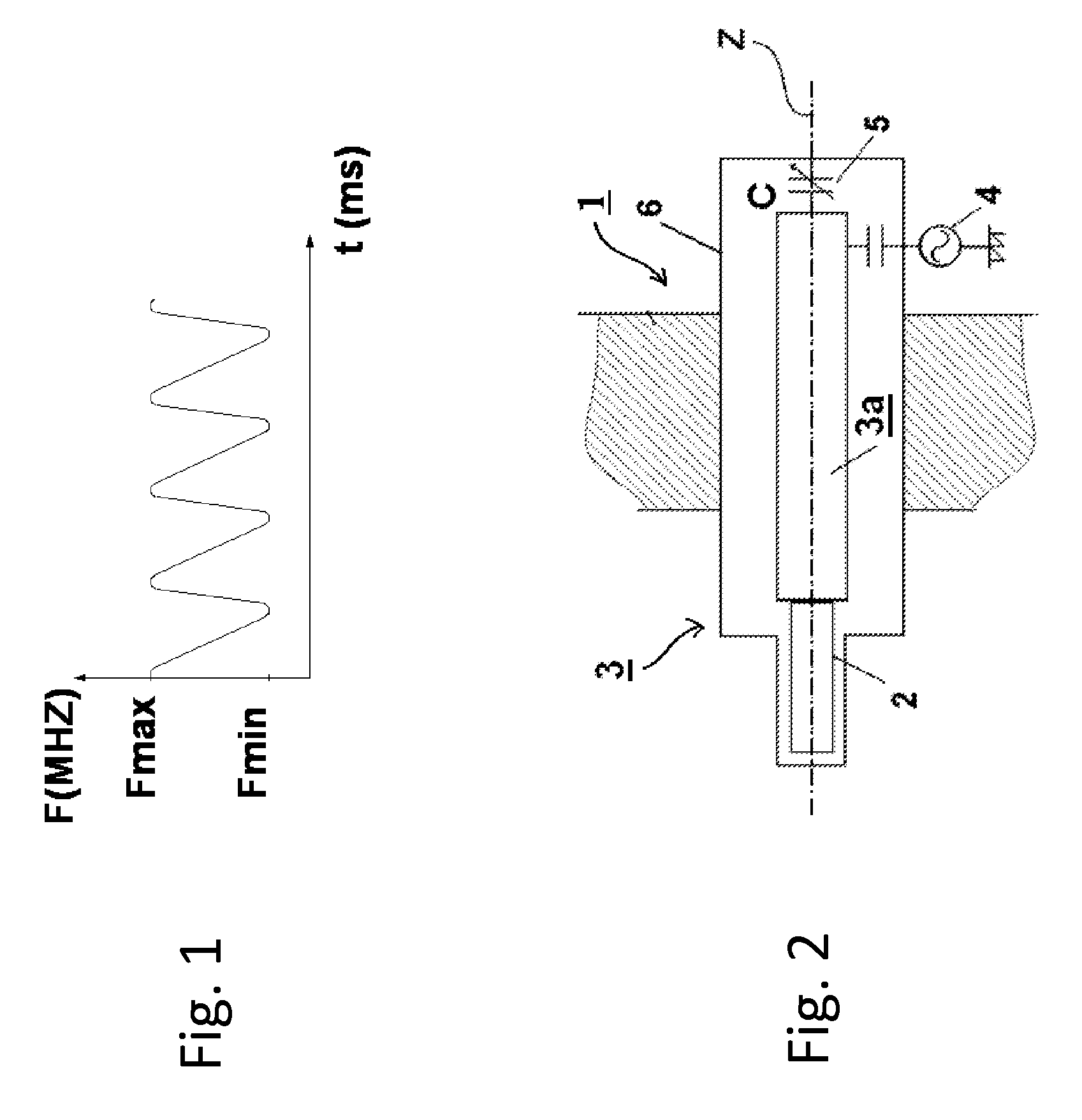
[0034]As a brief description of the known environment in which a RotCo according to the invention is used, FIG. 2 firstly shows in general a simplified RF structure of a synchrocyclotron 1. This RF structure comprises an accelerating dee 2 connected to an RF generator 4 via a coaxial transmission line 3 at the end of which there is RotCo 5. A conducting enclosure 6, which is grounded, surrounds the whole assembly. Such a structure is well known in the prior art and will therefore not be described in more detail.

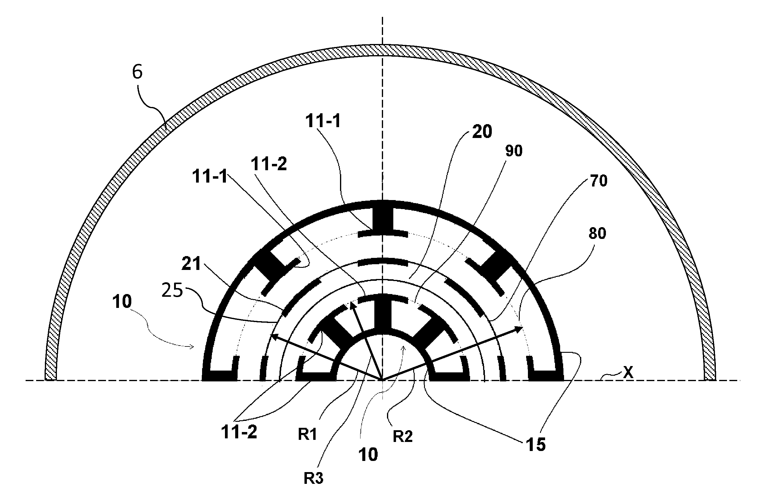
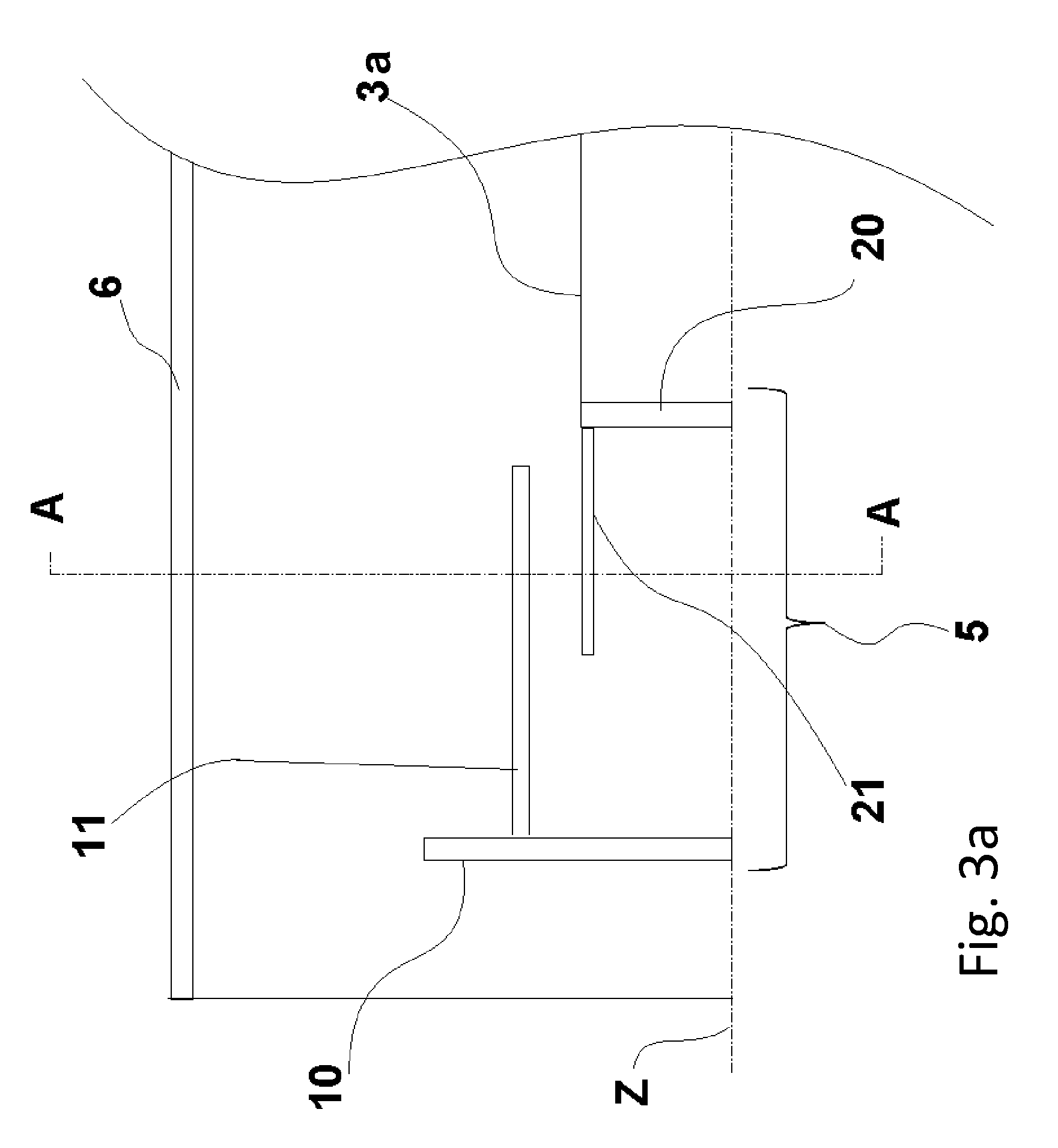
[0035]FIGS. 3a and 3b show schematically a longitudinal half-section and a transverse half-section (section “AA”) of a RotCo 5 according to the invention. The RotCo comprises a rotor 10 having a rotation axis Z and a stator 20 coaxial with the rotor. In this example, the rotation axis Z is the same as the longitudinal axis of the transmission line 3, but this is not essential. The rotor 10 comprises a plurality of rotor electrodes 11 that are distributed circumferentially, fo...


PUM


Abstract

A variable rotating capacitor or RotCo 5 that can be connected via a transmission line 3 to the dee 2 of a synchrocyclotron 1 so as to adjust a resonant frequency of the synchrocyclotron as a function of time and which comprises a cylindrical rotor 10 and a cylindrical stator 20 that are coaxial with the Z axis. The rotor comprises a plurality of circumferentially-distributed rotor electrodes 11 extending parallel to its rotation axis Z. The stator comprises a plurality of circumferentially-distributed stator electrodes 21 extending parallel to the rotation axis Z. Each stator electrode 21 consists of a single metal plate and all said plates are distributed over one and the same stator circumference 25. This makes it possible for the RF currents in the electrodes to be better distributed and thus reduces the local overheating.The present invention also relates to a synchrocyclotron comprising such a RotCo.

Description

[0001]This application is a 371 application of PCT / EP2012 / 051081, filed Jan. 25, 2012, which, in turn, claims priority of European Patent Application No.: 11142468.2, filed on Jan. 28, 2011 and U.S. Provisional Application No. 61 / 437,089 filed Jan. 28, 2011.FIELD OF THE INVENTION[0002]The present invention relates to the field of RF resonators for synchrocyclotrons and in particular to a variable rotating capacitor or RotCo for modulating the resonant frequency of such a resonator as a function of time.PRIOR ART[0003]One type of accelerator for accelerating particles to high energy is a cyclotron. A cyclotron accelerates charged particles—for example protons—which move in an axial magnetic field along a spiral path, by applying an alternating radiofrequency voltage (RF voltage) to one or more accelerating electrodes (called “dees”) contained in a vacuum chamber. This RF voltage produces an accelerating electric field in the space that separates the dees, thereby enabling the charged...

Claims


Application Information

Patent Timeline
Patent Type & Authority Patents(United States)
IPC IPC(8): H01G5/40H01G5/12H05H7/02H01G5/06H05H13/02H01G5/011
CPCH01G5/40H01G5/011H01G5/06H01G5/12H05H7/02H05H13/02
Inventor ABS, MICHEL
Owner ION BEAM APPL
Why Eureka
Try Eureka