Pump device having a detection device

a detection device and pump technology, applied in the field of pump devices, can solve the problems of rotor development at too high a speed, no pump at all or only reaching the operating state, and great danger

Active Publication Date: 2016-06-07
ECP ENTWICKLUNGSGMBH
View PDF240 Cites 74 Cited by
  • Summary
  • Abstract
  • Description
  • Claims
  • Application Information

AI Technical Summary

Benefits of technology

[0045]The end of a hollow catheter in which the pump is accommodated during a transport procedure can, for example, be provided as the holding device, with the pump being compressed by the surrounding hollow catheter until it is pushed out of the hollow catheter after being taken to the place of deployment, for example with the aid of a drive shaft or a further pulling force or catheter hose as a pushing tool. After the pump has been pushed out of the hollow catheter, the compressive holding force of the hollow catheter is removed so that the pump elements can elastically expand. This procedure can additionally be assisted by further measures such as a slow rotation of the pump rotor or a manipulation by additional pulling or pushing elements.
[0046]A sensor can be provided at the end of the hollow catheter which signals that the pump has been completely pushed out of the hollow catheter. It is thus ensured with a certain security that the pump has automatically expanded.

Problems solved by technology

There is thus the risk that the pump does not reach the operating state at all or only reaches it in part despite a corresponding actuation.
This contains a great danger, in particular on the deployment of such pumps in the biological sector, since either body fluids such as blood are damaged on the putting into operation of the pump or pump elements can get into a body fluid such as blood on damage to the pump.
In this case, impeller blades may break or may be operated in an unwanted manner in the transport state so that the rotor develops too high a speed due to a fluid resistance which is too low and damages components of the blood or of another body fluid.
If the speed is controlled or regulated, the pump would possibly work with insufficient output.

Method used


Image

  • Pump device having a detection device
  • Pump device having a detection device
  • Pump device having a detection device

Examples


Embodiment Construction

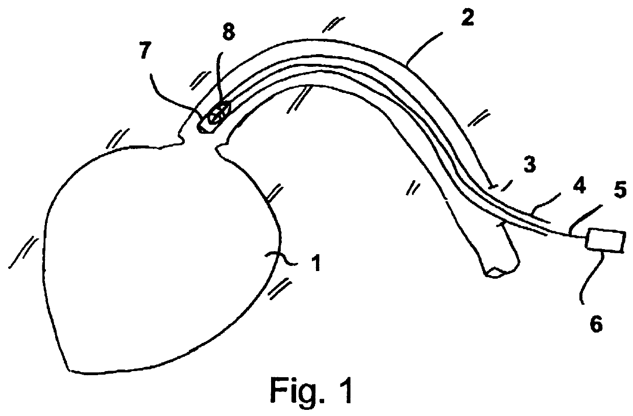
[0066]FIG. 1 schematically shows a ventricle 1 into which a blood vessel 2 opens through which a hollow catheter 4 is introduced by means of a sluice 3. The hollow catheter has a rotating shat 5 in its hollow space which is drivable at high revolutions, typically more than 10,000 revolutions per minute, by means of a motor 6.

[0067]The shaft 5 drives a pump 8 at the distal end 7 of the hollow catheter, said pump being compressed by the hollow catheter in the still compressed state at the end of the hollow catheter in the representation of FIG. 1.

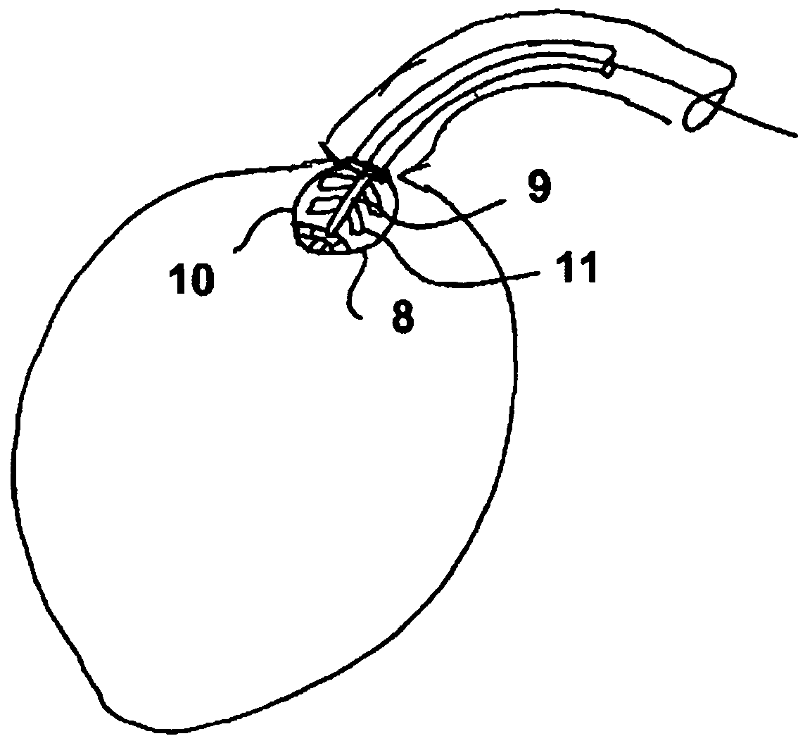
[0068]The pump can, for example, be pushed out of the end of the hollow catheter 4 into the ventricle 1 by means of the shaft 5 or by means of further elements not shown. The state which thus arises is shown in FIG. 2 where the pump 8 is shown in the expanded form. A rotor 9 is thus shown in schematic form in the interior of a pump housing 10.

[0069]The rotor 9 has impeller blades 11 which project radially from a hub and which are rolled up, f...


PUM


Abstract

The invention relates to a pump device having a pump (8) and an energy supply device (5, 18), wherein the pump has a conveying element (9, 11) which conveys a fluid by means of supplied energy, wherein the pump has a transport state and an operating state, and wherein at least one first element (9, 9a, 10, 10′, 11) of the pump has a different shape and/or size in the transport state than in the operating state. The operating safety of such a pump device is increased by a detection device (12, 20, 21, 22, 23, 24, 25, 27, 28, 29) which detects whether at least the first element is in the operating state with respect to shape and/or size by means of a sensor.

Description

BACKGROUND OF THE INVENTION[0001]The invention is in the field of mechanical engineering and precision engineering and relates to a pump device.[0002]Pumps are used for conveying fluids, in particular liquids, and are known in a variety of variants. Pumps are particularly interesting for many applications which either have a particularly small construction or whose design is changeable to be taken to a place of deployment with difficult access in a transport state, wherein an expanded state or an operating state can afterward be established in which individual elements of the pump have a different shape and / or size than in the transport state.[0003]Examples for such pumps are expandable catheter pumps which are introduced into a patient's body through a blood vessel and can be inserted up to and into a ventricle and can be expanded there.[0004]For this purpose, an expanding of a rotor of the pump and of a housing typically takes place. The rotor usually carries one or more impeller ...

Claims


Application Information

Patent Timeline
Patent Type & Authority Patents(United States)
IPC IPC(8): A61M29/00A61M1/10F04D29/24F04D29/18F04D15/00A61M1/12A61M60/13A61M60/216A61M60/422A61M60/538A61M60/871
CPCA61M1/1024A61M1/101A61M1/1086A61M1/122A61M1/125F04D15/0088F04D29/181F04D29/247A61M1/1029A61M1/1034A61M1/1072A61M2205/6018A61M25/00A61M2205/70A61M2210/125A61M60/414A61M60/216A61M60/13A61M60/538A61M60/422A61M60/148A61M2205/18A61M2205/3327F04D15/0254F04D29/043
Inventor SCHUMACHER, JOERG
Owner ECP ENTWICKLUNGSGMBH
Why Eureka
Try Eureka