Accelerator-pedal-counterforce control device and vehicle

a technology of counter-force control and accelerator pedal, which is applied in the direction of electric control, engine starters, machines/engines, etc., can solve the problems that the acceleration rate required by the vehicle may not necessarily be constant, and achieve the effects of enhancing the ease with which the accelerator pedal is operated, small acceleration, and large acceleration

Active Publication Date: 2016-06-14
HONDA MOTOR CO LTD
View PDF24 Cites 5 Cited by
  • Summary
  • Abstract
  • Description
  • Claims
  • Application Information

AI Technical Summary

Benefits of technology

[0009]The present invention has been made in view of the above problems. An object of the present invention is to provide an accelerator-pedal-reaction-force control apparatus and a vehicle, which are capable of enhancing the ease with which an accelerator pedal can be operated.
[0011]According to the present invention, the value produced by adding the predetermined quantity to the cruise opening is set as the reaction force increasing opening. If the driver of the vehicle depresses the accelerator pedal to the reaction force increasing opening, it is possible to achieve a rate of acceleration that depends on the present vehicle speed. Accordingly, it is possible to prevent the driver from feeling uneasy and uncomfortable concerning the action to accelerate the vehicle. In addition, the ease with which the accelerator pedal is operated can be enhanced.
[0012]The reaction force control unit may set the reaction force increasing opening such that the higher the vehicle speed is, the smaller the predetermined quantity becomes. With this arrangement, in a low vehicle speed range, it is possible for the driver to achieve a relatively large acceleration by depressing the accelerator pedal to the reaction force increasing opening. As a result, it is possible for the vehicle to achieve a rate of acceleration required to catch up with traffic, for example. Further, in a high vehicle speed range, it is possible for the driver to achieve a relatively small acceleration by maintaining the accelerator pedal at the reaction force increasing opening. As a result, it is possible to prevent the vehicle from being accelerated excessively, thereby preventing degradation in fuel consumption or electric energy consumption.
[0013]The reaction force control unit may set the reaction force increasing opening to an opening of the accelerator pedal, which enables an engine that is mounted on the vehicle to produce an output with better kinetic efficiency. In addition, the predetermined quantity may be established as a value for achieving an acceleration depending on each of the respective vehicle speeds, and for enabling an electric generator that is mounted on the vehicle to generate electric power under a drive power from the engine. With this arrangement, by depressing the accelerator pedal to the reaction force increasing opening, the driver is able to accelerate the vehicle while the engine produces an output with better kinetic efficiency. Consequently, it is possible to achieve a vehicle speed that depends on each of the respective vehicle speeds, and to enable the electric generator to generate electric energy while fuel consumption is good. In addition, it is possible to inform the driver concerning the opening of the accelerator pedal, thereby enabling better fuel consumption at each of the respective vehicle speeds.
[0015]With the above arrangement, if the first driving mode (in which the vehicle is driven with only a motor) can be selected, a reaction force control process for increasing the reaction force applied to the accelerator pedal is carried out upon switching from driving the vehicle with only the motor to driving the vehicle with at least the engine. Thus, it is possible to inform the driver that the vehicle is being driven with better fuel consumption. Further, if the first driving mode (in which the vehicle is driven with only the motor) cannot be selected, a reaction force control process is carried out, which uses a value produced by adding the predetermined quantity to the cruise opening as the reaction force increasing opening. Consequently, it is possible to prevent the driver from feeling uneasy and uncomfortable concerning the action to accelerate the vehicle. Therefore, both of the reaction force control processes are compatible with each other.

Problems solved by technology

However, when driving on actual roads, the rate of acceleration required by the vehicle may not necessarily be constant.

Method used


Image

  • Accelerator-pedal-counterforce control device and vehicle
  • Accelerator-pedal-counterforce control device and vehicle
  • Accelerator-pedal-counterforce control device and vehicle

Examples


embodiment

A. Embodiment

1. Arrangement of Vehicle 10

[1-1. Overall Arrangement]

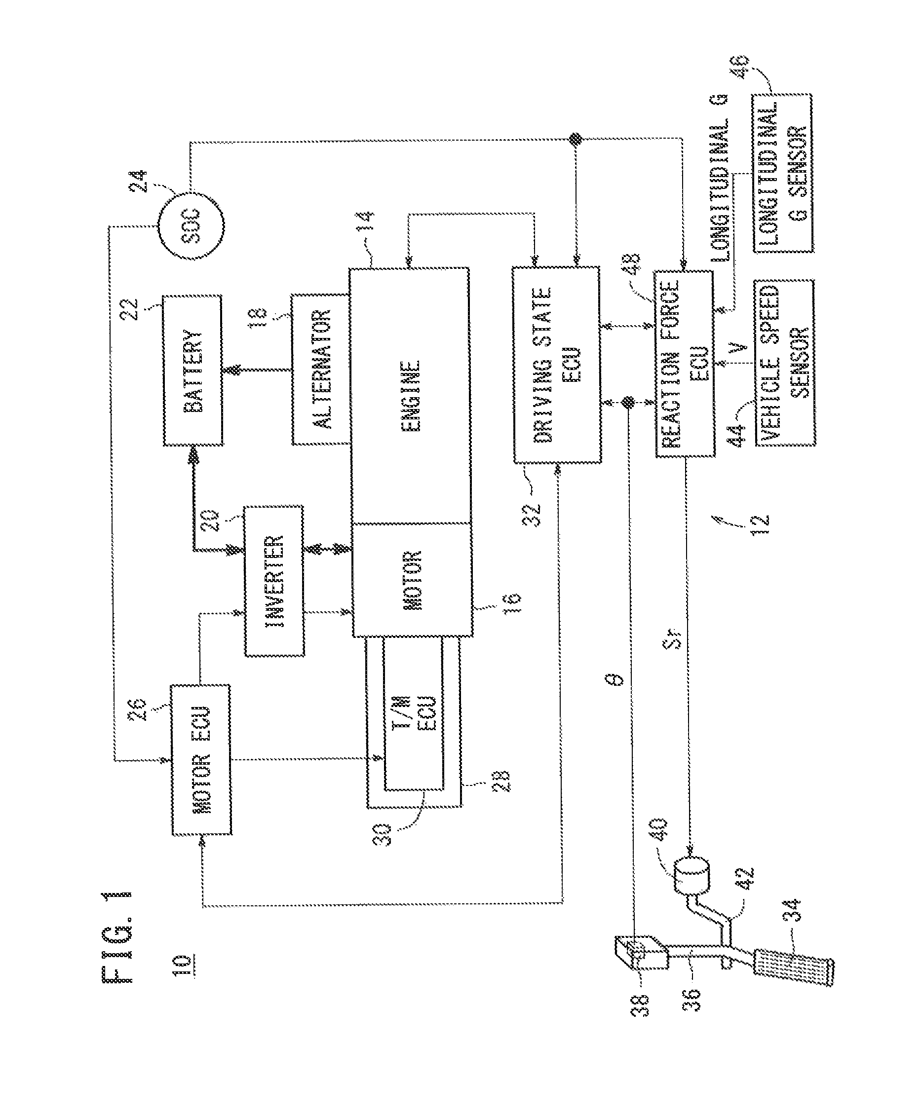
[0032]FIG. 1 shows in block form a vehicle 10 in which an accelerator-pedal-reaction-force control apparatus 12 (hereinafter referred to as a “reaction-force control apparatus 12” or a “control apparatus 12”) is incorporated according to an embodiment of the present invention. The vehicle 10 comprises a so-called hybrid vehicle, which includes an engine 14 and a traction motor 16 (hereinafter also referred to as a “motor 16”) as drive sources.

[0033]As shown in FIG. 1, in addition to the engine 14 (internal combustion engine) and the motor 16 (electric motor), the vehicle 10 also includes an alternator 18 (electric generator), an inverter 20, a battery 22 (electric storage device), an SOC sensor 24, a motor electronic control unit 26 (hereinafter referred to as a “motor ECU 26”), a transmission 28, a transmission electronic control unit 30 (hereinafter referred to as a “T / M ECU 30”), a driving state electronic control...


PUM


Abstract

An accelerator-pedal-counterforce control device for a vehicle, wherein a counterforce control means sets a value obtained by multiplying a prescribed quantity by a constant-speed position as a counterforce-increase position. The counterforce-increase position is a position of the accelerator pedal at which the counterforce on the accelerator pedal is increased from the base counterforce. The constant-speed position is a position of the accelerator pedal at which constant travel at the current vehicle speed is possible. The prescribed quantity is set as a value for achieving forward-rear acceleration according to each vehicle speed.

Description

TECHNICAL FIELD[0001]The present invention relates to an accelerator-pedal-reaction-force control apparatus (accelerator-pedal-counterforce control device) as well as to a vehicle in which a reaction force control unit is included for controlling a reaction force applied to an accelerator pedal.BACKGROUND ART[0002]International Publication No. WO 2011 / 148753 (hereinafter referred to as “WO 2011 / 148753 A1”) discloses an arrangement for controlling a pressing force (reaction force) on an accelerator pedal 32 in a hybrid vehicle.[0003]According to WO 2011 / 148753 A1, an accelerator opening threshold value is set to a greater one of the values of a first accelerator opening and a second accelerator opening for each of respective vehicle speeds ([0036]). The accelerator opening threshold value is a threshold value for increasing a pressing force on the accelerator pedal 32, so that the pressing force is greater than a base pressing force ([0033]). The first accelerator opening is an accel...

Claims


Application Information

Patent Timeline
Patent Type & Authority Patents(United States)
IPC IPC(8): B60K26/02B60K6/54B60W20/00B60K6/48B60K26/04B60W10/00B60W50/16F02D41/06B60K6/52F02N11/08
CPCB60K6/48B60W20/40B60K26/021B60K6/54B60K26/04B60W10/00B60W20/00B60W20/20B60W50/16F02D41/06Y02T10/6221B60K6/52B60K2026/023F02N11/0822F02N2200/101B60K2006/4825Y02T10/6265Y10S903/902Y02T10/6252B60W2520/10B60W2540/10Y02T10/62
Inventor MARUYAMA, KOHEISEN, NAOTOYOSHIMURA, TAKAYUKINEBUYA, HIDETOKINOSHITA, TOMOYUKI
Owner HONDA MOTOR CO LTD
Why Eureka
Try Eureka