
System for and method of displaying information without need for a combiner alignment detector

a technology of combiner and display device, applied in the field of displays, can solve the problems of significant alignment errors, misleading information, and inability to accurately display information, and achieve the effect of avoiding alignment errors and avoiding stowage errors

Active Publication Date: 2016-06-14
ROCKWELL COLLINS INC
View PDF527 Cites 78 Cited by
  • Summary
  • Abstract
  • Description
  • Claims
  • Application Information

AI Technical Summary

Benefits of technology

This patent describes a head up display that uses a micro image source and collimating optics to provide information to the user without the need for a combiner alignment detector. The display includes a collimator, a substrate waveguide, and a stow mechanism. The collimated light travels from the input to the output within the substrate waveguide by total internal reflection. An input and output diffraction grating work together to achieve a periscopic effect. The technical effects of this invention include improved user experience and reduced complexity of the display.

Problems solved by technology

Small deflections in the position of the combiner with respect to the projection optics can cause significant alignment errors associated with the information or symbology projected by the optics onto the combiner.
Alignment errors associated with symbology and its placement in the real world view can result in misleading information.
Imprecision in the stow mechanism can contribute to alignment errors when the combiner is moved to and from the operational position and the stowed position.
CADs can be disadvantageous for a number of reasons.
First, the CAD adds to the cost of the HUD and can be expensive to manufacture.
Second, the CAD requires calibration which adds to manufacturing and service costs.
Third, the CAD can be subject to failure.
Fourth, a conventional CAD can give an erroneous ALIGN HUD message that may result from stray light, sunlight, dirt, or unknown electrical faults.

Method used


Image

  • System for and method of displaying information without need for a combiner alignment detector
  • System for and method of displaying information without need for a combiner alignment detector
  • System for and method of displaying information without need for a combiner alignment detector

Examples


Embodiment Construction

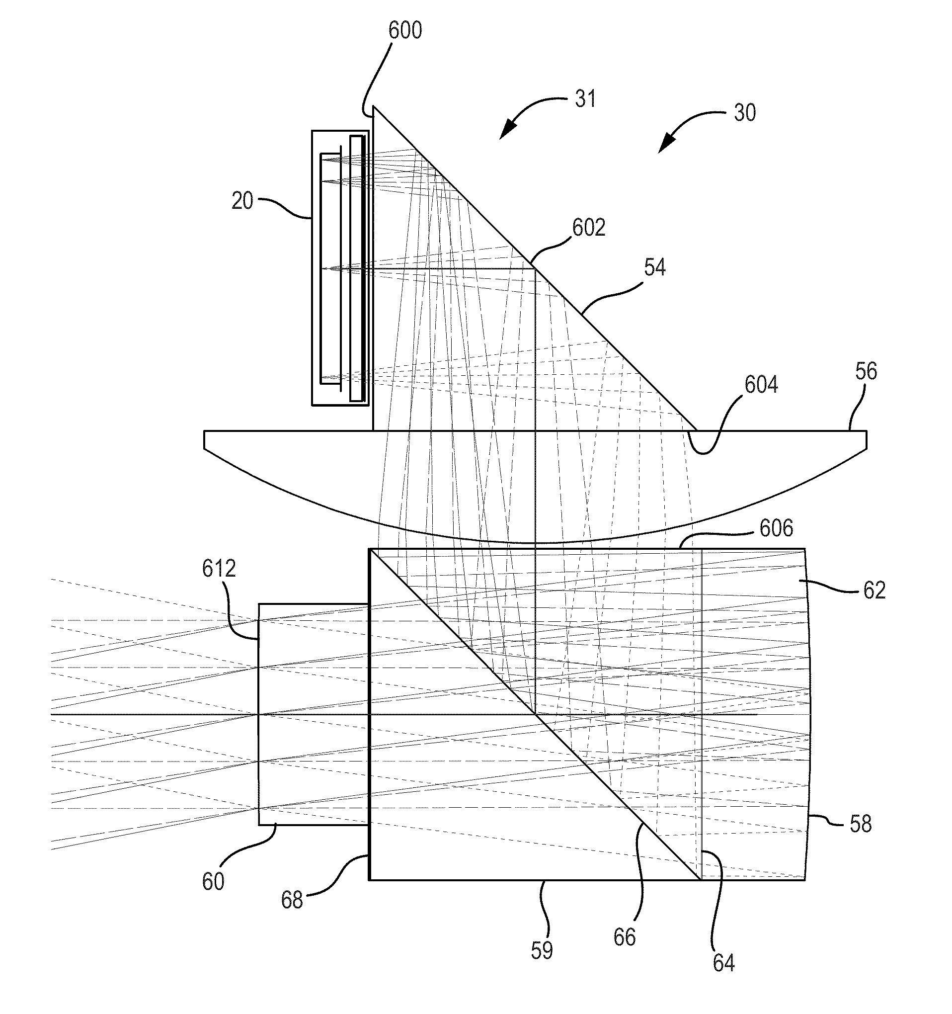
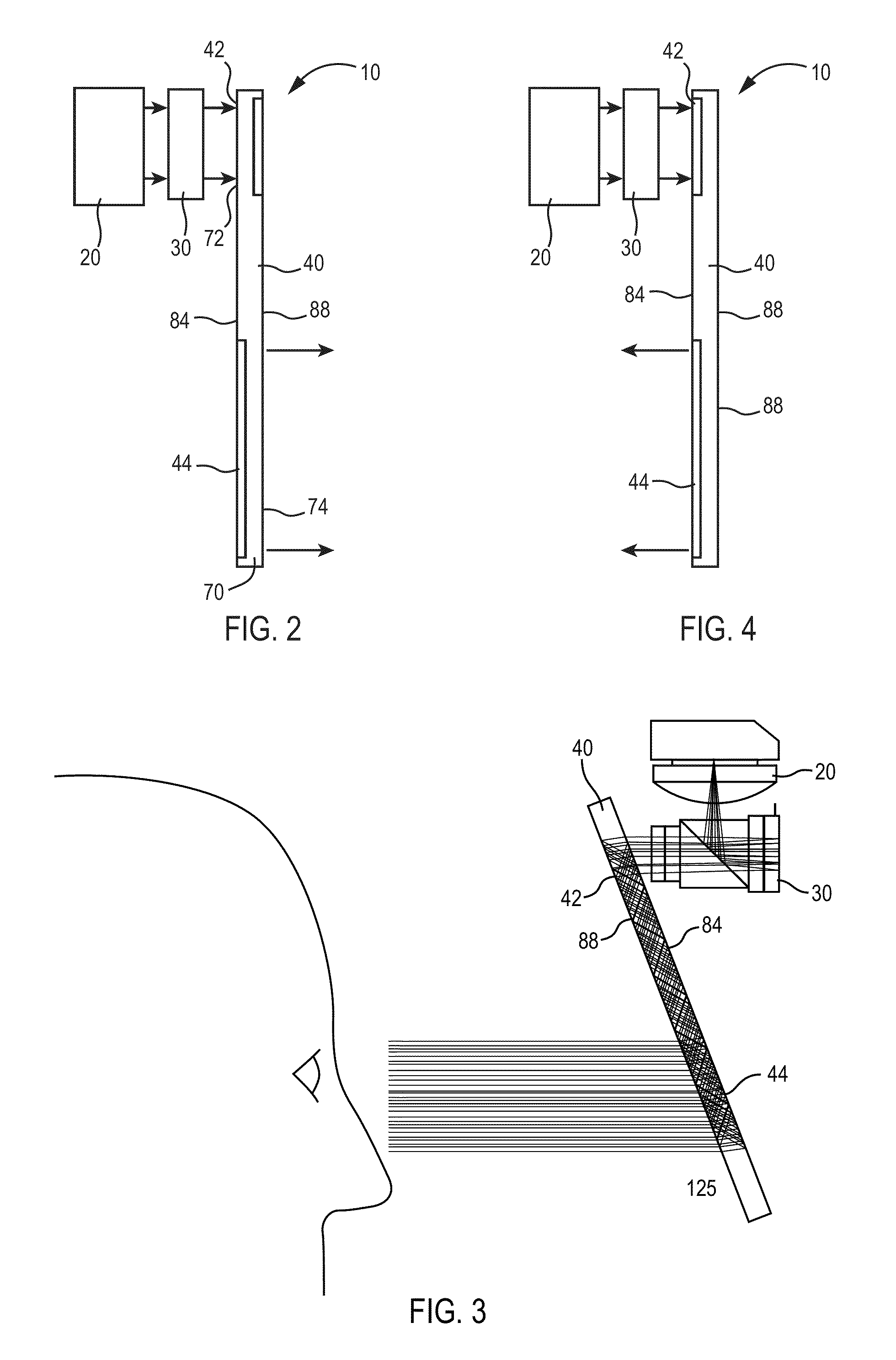
[0020]Before describing in detail the particular improved system and method, it should be observed that the invention includes, but is not limited to, a novel structural combination of optical components and not in the particular detailed configurations thereof. Accordingly, the structure, methods, functions, control and arrangement of components have been illustrated in the drawings by readily understandable block representations and schematic drawings, in order not to obscure the disclosure with structural details which will be readily apparent to those skilled in the art, having the benefit of the description herein. Further, the invention is not limited to the particular embodiments depicted in the exemplary diagrams, but should be construed in accordance with the language in the claims.

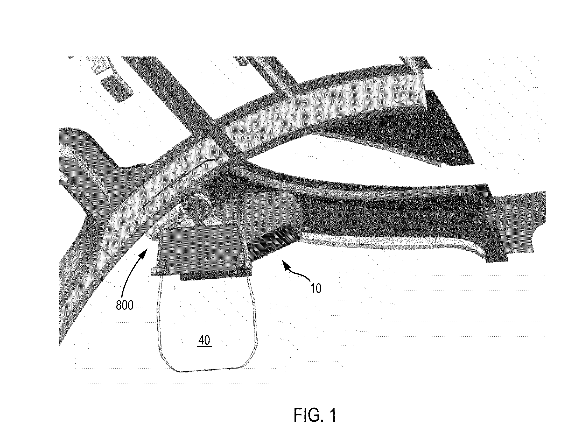
[0021]With reference to FIG. 1, a display, such as, a head up display (HUD) system 10, can be utilized in various applications, including aviation, medical, naval, targeting, ground based, milita...


PUM


Abstract

A display can be utilized with an image source. The display includes a collimator and a substrate waveguide. The substrate waveguide sees collimated light from the collimator at an input and provides the collimated light to an output. The collimated light travels from the input to the output within the substrate by total internal reflection. An input diffraction grating is disposed in a first area at the input and an output diffraction grating is disposed in a second area at the output. The second diffraction grating is matched to the first diffraction grating. A combiner alignment detector is not required due to the periscopic effect according to one embodiment.

Description

CROSS REFERENCE TO RELATED APPLICATIONS[0001]The present application is a continuation-in-part of and claims the benefit of priority to: U.S. patent application Ser. No. 13 / 250,621 filed on Sep. 30, 2011 entitled “System For And Method of Catadioptric Collimation In A Compact Head Up Display (HUD)”, now U.S. Pat. No. 8,634,139, incorporated herein by reference in its entirety and assigned to the assignee of the present application; “U.S. patent application Ser. No. 13 / 250,940, entitled, “Head Up Display (HUD) Utilizing Diffractive Gratings Having Optimized Efficiency,” filed on Sep. 30, 2011, incorporated herein by reference in its entirety, and assigned to the assignee of the present application; U.S. patent application Ser. No. 13 / 250,858, entitled, “Ultra-Compact HUD Utilizing Waveguide Pupil Expander With Surface Relief Gratings In High Refractive Index Materials,” filed on Sep. 30, 2011, incorporated herein by reference in its entirety, and assigned to the assignee of the prese...

Claims


Application Information

Patent Timeline
IPC IPC(8): G02B17/08F21V8/00G02B5/30G02B27/01
CPCG02B6/0016G02B27/0101G02B5/30G02B27/0149G02B27/0103G02B2027/0123G02B2027/0125G02B2027/0118G02B5/18G02B2027/015G02B2027/0156G02B6/0035G02B6/00G02B6/005G02B17/0884G02B27/0081G02B27/0172G02B27/0176G02B27/283G02B27/30G02B2027/0154
Inventor BROWN, ROBERT D.STAHL, KURT A.BURNS, LINCOLN J.
Owner ROCKWELL COLLINS INC
Features
  • Generate Ideas
  • Intellectual Property
  • Life Sciences
  • Materials
  • Tech Scout
  • Unparalleled Data Quality
  • Higher Quality Content
  • 60% Fewer Hallucinations
Learn More