Valve apparatus for high pressure gas containers

a gas container and valve apparatus technology, applied in the field of high-pressure valves, can solve the problem of difficult fabrication of leakage-free solenoid valves, and achieve the effect of high-pressure seal structures

Active Publication Date: 2016-06-21
LHYMN SUE H +1
View PDF26 Cites 5 Cited by
  • Summary
  • Abstract
  • Description
  • Claims
  • Application Information

AI Technical Summary

Benefits of technology

[0004]The invention presents a valve apparatus that prevents a seal member from falling off from a movable plunger when sealing is performed via the seal member fitted in the movable plunger and also presents a high pressure seal structure.
[0014]With the above aspect of the invention, the pilot seal member is trapped inside a hollow cavity, pressed by a slidable pilot plunger on the one side and abutting against the shoulder step on the other side such that the pilot seal cannot fall off from the movable core while performing the sealing function by being in contact with the pilot seat when the coil is de-energized.
[0017]According to a sixth aspect and feature of the present invention, the tapered cone seal member has O-ring grooves for installing O-rings in double or multiple configurations. The mating valve body seat is also of tapered cone shape, and thus the airtight sealing is achieved.
[0018]According to a seventh aspect and feature of the present invention, a temperature sensor is installed in a sensor chamber inside a tank. As such the temperature sensor is held in an ambient environment by means of a sealed chamber. The chamber is open to the outside atmosphere through a sealed passage and an accurate reading of temperature inside the tank is possible.
[0020]According to a ninth aspect and feature of the present invention, filter discs of simple design and compact geometry are provided in the valve. The first filter (outlet filter) is inside the gas supply port and the second filter (inlet filter) is disposed between the manual valve and the excess flow shut-off device. The third filter in arranged inside the check valve (check valve filter). Because of a compact size and simple geometry, the disc filters can be arranged in a small valve assembly at inlet, outlet, and fill port. The critical sealing members of solenoid and manual valves are thus protected from dust particles or contaminants by neighboring inlet and outlet filters.
[0023]According to a twelfth aspect and feature of the present invention, a reliable seal material and seal structure are presented. A single layer, a double layer, and a multi-layer structure are proposed for use at 10,000 psi gas pressure. They basically deform slightly for sealing but do not deform destructively.

Problems solved by technology

For a hydrogen tank used for a fuel cell-driven vehicle, it is often pressurized up to 700 Bar (10,000 psi) and leakage-free solenoid valve is difficult to fabricate and currently is not available commercially.
Often such disc falls off from the recess to lose the gas tightness at the orifice opening.

Method used


Image

  • Valve apparatus for high pressure gas containers
  • Valve apparatus for high pressure gas containers
  • Valve apparatus for high pressure gas containers

Examples


Embodiment Construction

[0037]The explanation of the present invention is given according to FIGS. 1 to 11 in the following section.

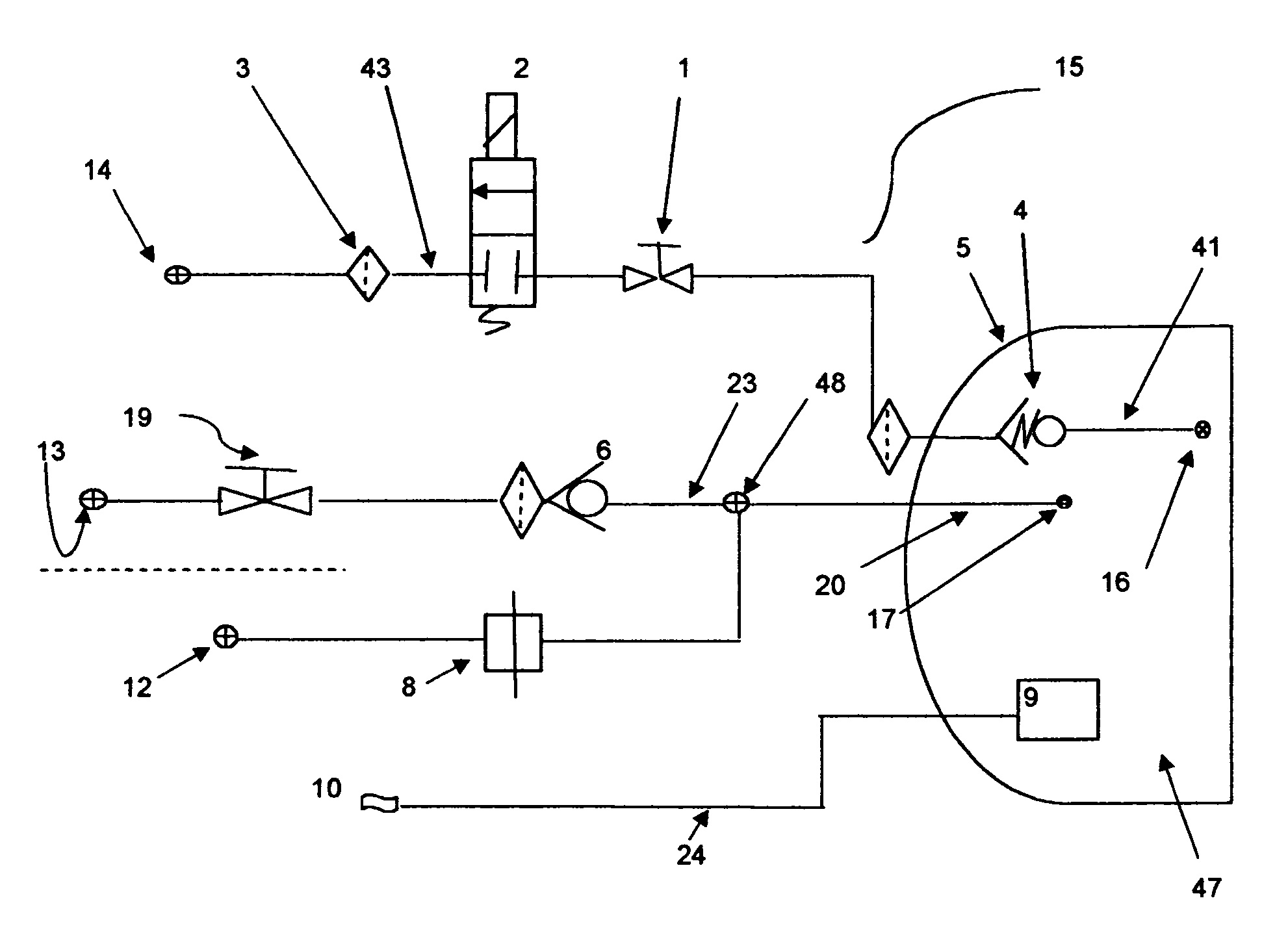
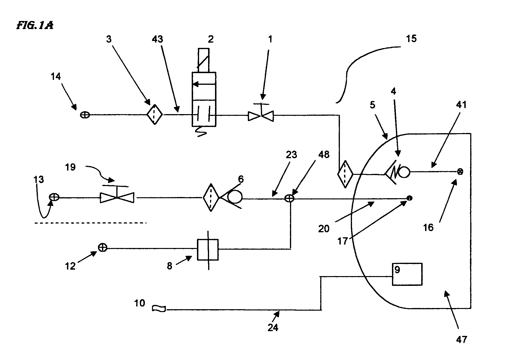
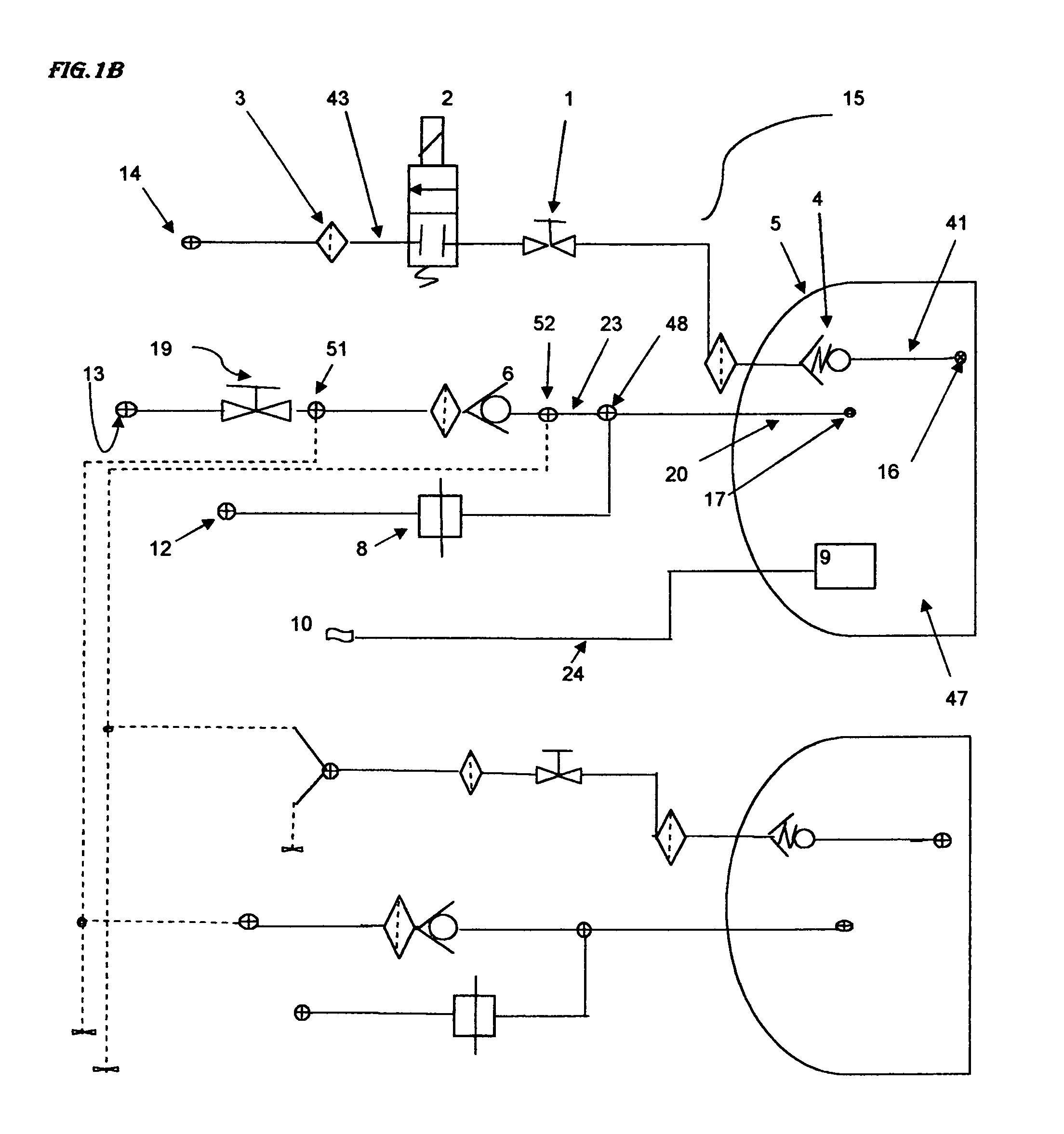
[0038]First, the architecture of the valve assembly is explained by reference to FIG. 1(A). The valve apparatus 15 consists of a fuel supply passage 14, a gas filling passage 13, a gas discharge PRD line 12 in case of fire, and a temperature sensor port 10. The gas charging passage 13 and discharge passage 12 are joined upstream and communicate with the gas cylinder 5 at communication passage 17.

[0039]The fuel supply passage 14 starts from the input 16, and then through an excess flow shut-off device 4, an inlet filter 18, a manual open / close valve 1, an electromagnetic solenoid on / off valve 2, an outlet filter 3, and finally outlet gas supply port 14.

[0040]The fuel shut-off valve consists of a manual valve 1 and a solenoid valve 2. The gas charging passage 13 is composed of a check valve 6 and an open / close manual valve 19. The manual valve 19 is arranged outside of the valve...


PUM


Abstract

A valve apparatus is comprised of a solenoid valve, a manual valve, a pressure relief device, a check valve, an excess flow shut-off device, and a temperature sensor. The temperature sensor is arranged inside the tank in an ambient atmosphere. The sealing member is prevented from falling off from the recess by a floating seal structure. The sealing effectiveness is improved by employing a double seal configuration and also by a smooth surface roughness. A high pressure seal structure is presented. The improved pressure relief device design for 75 MPa application has been presented.

Description

BACKGROUND OF THE INVENTION[0001]The present invention relates to a high pressure valve for hydrogen gas, natural gas, or other gases. Specifically the present invention pertains to a solenoid valve and a manual valve used at a high pressure. Particularly the solenoid valve is suitable for use in a high pressure hydrogen gas tank for vehicles driven by a fuel cell. For a hydrogen tank used for a fuel cell-driven vehicle, it is often pressurized up to 700 Bar (10,000 psi) and leakage-free solenoid valve is difficult to fabricate and currently is not available commercially. Thus there is a need to improve the sealing design for gastight valve.[0002]In prior art, the disc shape seal is inserted into the recess created in the stem or sealing assembly. Often such disc falls off from the recess to lose the gas tightness at the orifice opening. This invention attempts to eliminate such separation of sealing member from the seal-holding recess in the sealing assembly. Such objective is anot...

Claims


Application Information

Patent Timeline
Patent Type & Authority Patents(United States)
IPC IPC(8): F16K21/00F16K1/36F16K17/38F16K25/00F16K1/30F16K31/42
CPCF16K1/30F16K1/304F16K1/36F16K17/383F16K25/005F16K31/42Y10T137/86292
Inventor LHYMN, SUE H.LHYMN, CHRIS
Owner LHYMN SUE H
Why Eureka
Try Eureka