Light source device

a technology of light source and light source, which is applied in the direction of outdoor lighting, semiconductor devices of light source, lighting and heating apparatus, etc., can solve the problems of limited light emission angle of light bulb having led light source, weak light intensity at a side oblique to the light-emitting side of light source, and insufficient to meet the requirement of omni-directional lighting, etc., to achieve great light-emitting uniformity

Active Publication Date: 2016-06-21
EPISTAR CORP
View PDF8 Cites 2 Cited by
  • Summary
  • Abstract
  • Description
  • Claims
  • Application Information

AI Technical Summary

Benefits of technology

[0007]Accordingly, the present invention is directed to a light source device which is able to provide omni-directional lighting.
[0025]According to an embodiment of the present invention, the distance between the center of the bottom and the light exiting surface from one end where the first light exiting region connects to the concave region to another end where the first light exiting region connects the second light exiting region is increasing smoothly and gradually.
[0027]According to an embodiment of the present invention, the distance between the center of the bottom and the light exiting surface from one end where the first light exiting region connects to the second light exiting region to another end where the second light exiting region connects to the bottom of the molding lens is increasing smoothly and gradually.
[0028]According to an embodiment of the present invention, the distance between the center of the bottom and the light exiting surface from one end where the first light exiting region connects to the second light exiting region to another end where the second light exiting region connects to the bottom of the molding lens is decreasing.
[0033]Based on the abovementioned description, the embodiments of the present invention provide various molding lenses with various shapes for encapsulating the LED chip of the light source device. In detail, the light exiting surface of the molding lens includes a concave portion, a first light exiting region surrounding the concave portion and a second light exiting region surrounding the first light exiting region, and the first light exiting region connects between the concave portion and the second light exiting region. The concave portion is capable of reflecting the light emitted by the LED chip to the first light exiting region and the second light exiting region. Thereby, with the disposition of the molding lens, the light source device can provide wide angle light-emitting effect and great light-emitting uniformity.

Problems solved by technology

Therefore, if the LED light source is directly applied in a conventional light bulb without any modification, the light emission angle of the light bulb having the LED light source would be restricted, and particularly, the light intensity at a side oblique to the light-emitting side of the light source is even weaker.
However, it is still not enough to meet the requirement of the omni-directional lighting.

Method used


Image

  • Light source device
  • Light source device
  • Light source device

Examples


Embodiment Construction

[0048]Reference will now be made in detail to the present preferred embodiments of the invention, examples of which are illustrated in the accompanying drawings. Wherever possible, the same reference numbers are used in the drawings and the description to refer to the same or like parts.

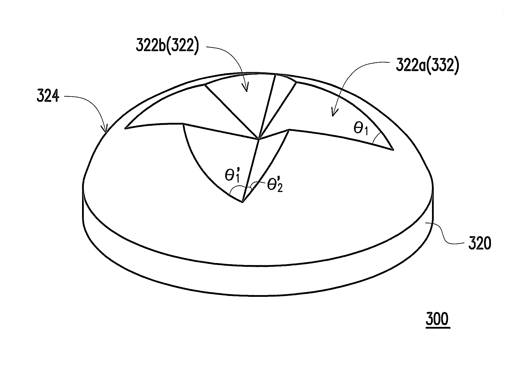
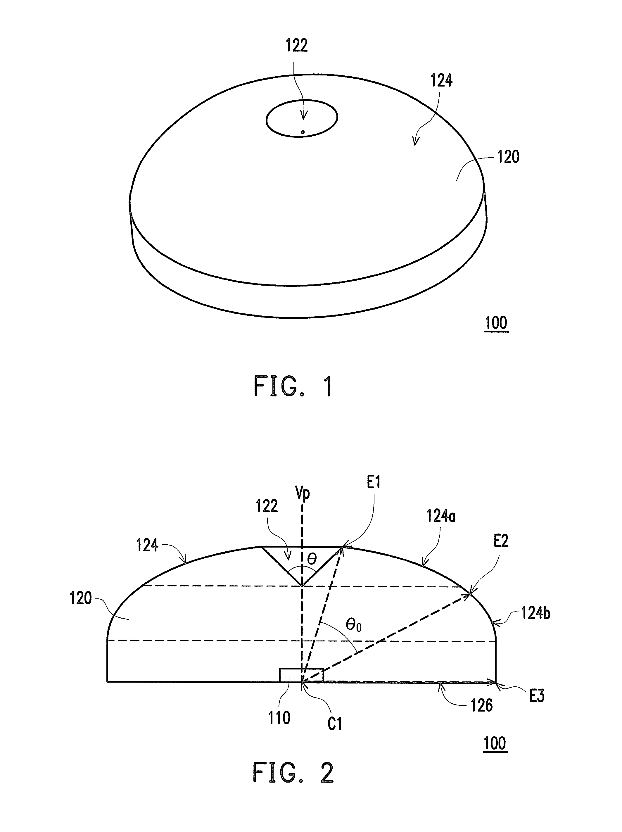
[0049]FIG. 1 illustrates a schematic view of a light source device according to an embodiment of the invention. FIG. 2 illustrates a cross-sectional view of the light source device in FIG. 1. Referring to FIG. 1 and FIG. 2, a light source device 100 of the present embodiment includes a light emitting diode (LED) chip 110 (the light emitting chip shown in FIG. 13 is labeled as 410) and a molding lens 120. The molding lens 120 is directly formed on the LED chip 110 by insert molding or injection molding process, and includes a center C1 of a bottom 126 where the LED chip 110 located at and a light exiting surface 124 (the light exiting surface shown in FIG. 6 is labeled as 224, and the light exiting su...


PUM


Abstract

A light source device including a light emitting diode (LED) chip and a molding lens is provided. The molding lens is directly formed on the LED chip and includes a center of a bottom where the LED chip located at and a light exiting surface formed corresponding to the center. The light exiting surface comprises a concave portion, a first light exiting region surrounding the concave portion and a second light exiting region surrounding the first light exiting region. The first light exiting region connects between the concave portion and the second light exiting region.

Description

CROSS-REFERENCE TO RELATED APPLICATION[0001]This application claims the priority benefits of U.S. provisional application Ser. No. 61 / 931,695, filed on Jan. 27, 2014. The entirety of the above-mentioned patent application is hereby incorporated by reference herein and made a part of this specification.BACKGROUND OF THE INVENTION[0002]1. Field of the Invention[0003]The present invention generally relates to a light source device. More particularly, the present invention relates to a light source device having a molding lens.[0004]2. Description of Related Art[0005]In the recent years, along with the progression of semiconductor technology, light emitting diode (LED) is able to emit light beam having high luminous intensity, and the luminous efficiency of the LED is constantly improved. Compared to some conventional light sources, the LED light source has the advantages of energy efficient, small size and long life expectancy. Therefore, the conventional light sources are gradually re...

Claims


Application Information

Patent Timeline
Patent Type & Authority Patents(United States)
IPC IPC(8): F21V5/04F21S6/00F21W131/103
CPCF21V5/04F21S6/003F21W2131/103F21Y2101/02F21Y2115/10
Inventor YE, ZHI-TINGCHIEN, FEN-REN
Owner EPISTAR CORP
Why Eureka
Try Eureka