
NA reduction in fiber optical couplers

a technology of optical couplers and numeric apertures, applied in the field of optical couplers, can solve the problems of increasing the numerical aperture of light, difficult and less efficient coupling into other devices, and light rays emerging, so as to reduce the taper ratio, reduce the increase in na, and increase the overall performance

Active Publication Date: 2016-06-28
OFS FITEL LLC
View PDF12 Cites 0 Cited by
  • Summary
  • Abstract
  • Description
  • Claims
  • Application Information

AI Technical Summary

Benefits of technology

The design reduces the increase in numerical aperture at the output port, enhancing light confinement and brightness, allowing for more efficient coupling and improved performance compared to prior art TFB couplers.

Problems solved by technology

One problem with conventional TFB couplers is that the tapering process increases the NA of the light at the output face 12 (as noted above), which, in turn, means that light rays emerging from output face 12 diverge more, which makes coupling into other devices (e.g., into output fiber 19) more difficult and less efficient.
Although in an ideal TFB brightness would be conserved between the input and output, the numerical aperture of the light is still increased, which is undesirable for many applications.

Method used


Image

  • NA reduction in fiber optical couplers
  • NA reduction in fiber optical couplers
  • NA reduction in fiber optical couplers

Examples


experiment i

Thinner Fiber Claddings in the Second Section Configured by Etching Process

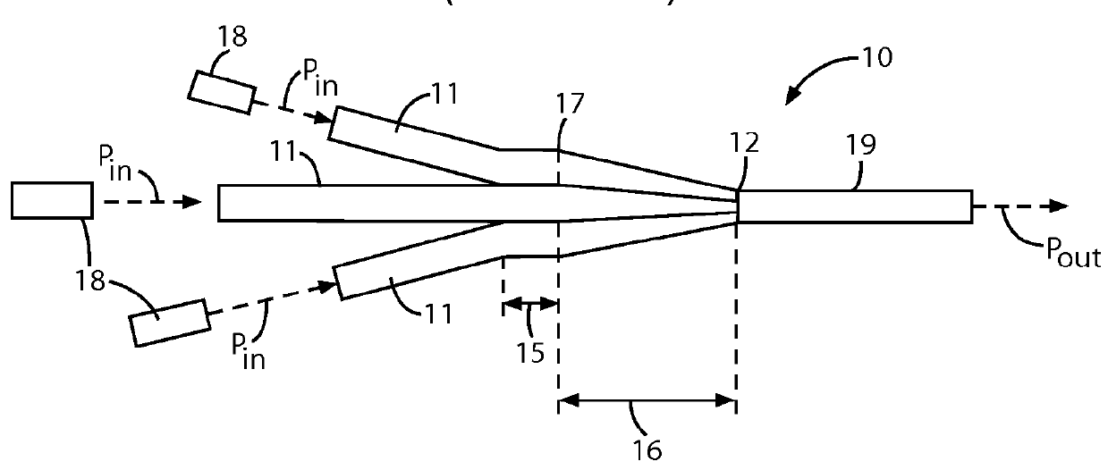
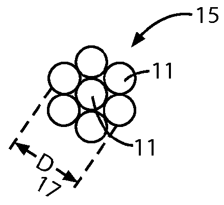
[0069]Multimode silica fibers with undoped cores and F-doped claddings were used in all cases described below. We compared the measured NA of an input fiber (105 μm core diameter, 125 μm cladding outside diameter, and 0.22 NA) to the output of a seven-fiber, multimode TFB of the type shown in FIGS. 1 and 2 but modified in accordance with this embodiment of our invention. The TFB was fabricated with a 10% TDR to reduce an initial diameter at interface 17 of 330 μm to a final diameter at interface 17 of 300 μm. Light was launched to fully-fill the NA of each fiber.

[0070]The NA of light in the 10% taper was measured to be approximately 0.02 larger than light in the input fiber (10% larger than the NA of the input fiber). This NA increase is consistent with that predicted by optical theory.

[0071]Since the NA increase of a TFB is due to light reflecting off of the core / cladding interface inside the tapered second ...

experiment ii

Thinner Fiber Claddings in Second Section Configured by Use of Thinner As-Drawn Fibers

[0076]Multimode silica fibers with undoped cores and F-doped claddings were used in all cases described below. A result similar to that of Experiment I was achieved by forming the second section of fibers that, as drawn, had smaller diameters than the fibers of first section, but the core diameters were the same (105 μm) in both sections. These separate sections were fusion spliced to one another to form a TFB of the type shown in FIGS. 1 and 2 but modified in accordance with this embodiment of our invention. The second section, and only this section, was then tapered by techniques well known in the TFB art.

[0077]All fibers of the second section had a 105 μm diameter core, but had different outside diameter claddings (116 μm, or 111 μm).

[0078]The NA results were comparable to those of Experiment I.

[0079]It is to be understood that the above-described arrangements are merely illustrative of the many...


PUM


Abstract

A fiber optical coupler comprises a bundle of optical fibers configured to couple light from a multiplicity of input light sources to an output port, each of the fibers comprising a multimode fiber having a core region and a cladding region surrounding the core region. The bundle has first and second axial sections arranged in tandem and adiabatically coupled to one another via a transition zone that includes an optical interface. Within the first section, the ratio of the cross-sectional core area of each of at least some of the fibers to the total cross-sectional area of each of those fibers is given by R1, and within the second section, the ratio of the cross-sectional core area of each of at least some of the fibers to the total cross-sectional area of each of those fibers is given by R2>R1, where R2 is substantially constant along the axial length of the second section. In one embodiment, the second section is tapered from a larger diameter at the optical interface to a smaller diameter at the output port. Methods of making such optical couplers are also described.

Description

CROSS-REFERENCE TO RELATED APPLICATIONS[0001]This application claims the benefit of U.S. Provisional Application 61 / 384,959, filed Sep. 21, 2010, which is incorporated herein by reference.BACKGROUND OF THE INVENTION[0002]1. Field of the Invention[0003]This invention relates to optical couplers, and, more particularly, to reducing the increase of numeric aperture (NA) in fiber optical couplers, including tapered-fiber-bundle (TFB) optical couplers.[0004]2. Discussion of the Related Art[0005]Applications that utilize high power light (optical) sources are diverse, ranging from machining and welding to pumping optical amplifiers and lasers. In these applications, a tapered fiber bundle (TFB) optical coupler is often used to couple multiple light inputs from multiple light sources into a single optical output port. [See, for example, DiGiovanni & Stentz, U.S. Pat. No. 5,864,644 (1999) and DiGiovanni & Tipton, U.S. Pat. No. 5,935,288 (1999), both of which are incorporated herein by refer...

Claims


Application Information

Patent Timeline
Patent Type & Authority Patents(United States)
IPC IPC(8): G02B6/26G02B6/24G02B6/28
CPCG02B6/262G02B6/24G02B6/2835
Inventor HOLLAND, WILLIAM R.STRACHAN, WILLIAM J.
Owner OFS FITEL LLC
Learn More