X-ray tomosynthesis imaging device and calibration method of an X-ray tomosynthesis imaging device

a technology of x-ray tomosynthesis and imaging device, which is applied in the direction of image enhancement, patient positioning for diagnostics, instruments, etc., can solve the problems of not being able to cope with aging degradation, not being able to install x-ray source and x-ray detector with high-precision alignment, etc., to achieve easy calibration, easy to determine, and precise reconstruction

Active Publication Date: 2016-07-05
FUJIFILM CORP
View PDF14 Cites 9 Cited by
  • Summary
  • Abstract
  • Description
  • Claims
  • Application Information

AI Technical Summary

Benefits of technology

[0014]An object of the present invention is to solve the problems based on the conventional techniques and to provide an X-ray imaging device that can correct a misalignment even when a movement axis of an X-ray source has the misalignment with respect to an X-ray detector, that can obtain a high-precision synthesis image (tomosynthesis image) of a cross section at a predetermined position of a subject, and that furthermore can suppress aging degradation of the misalignment in addition to the correction of the misalignment described above and a calibration method therefor.
[0035]According to the present invention, even when the movement axis of the X-ray source has a misalignment with respect to the X-ray detector, it is possible to correct the misalignment. Accordingly, at the time of reconstruction of tomosynthesis, it is possible to perform precise reconstruction using the respective images. As a result, it is possible to obtain a high-precision synthesis image (tomosynthesis image) of a cross section at a predetermined position of a subject.
[0036]Moreover, according to the invention, it is possible to easily determine whether it is necessary to update calibration data for correcting the misalignment of the movement axis of the X-ray source with the X-ray detector depending on an aging variation. Accordingly, it is possible to easily see whether to perform calibration and it is thus possible to perform the calibration if necessary. As a result, it is possible to suppress an influence of the aging variation, and it is thus possible to always perform precise reconstruction of tomosynthesis, and to always obtain a high-precision synthesis image (tomosynthesis image) of a cross section at a predetermined position of a subject.

Problems solved by technology

Particularly, in an X-ray imaging device using an overhead traveling X-ray source, the X-ray source and the X-ray detector (X-ray image sensor) are not integrated as a unified body and it is thus not easy to install the X-ray source and the X-ray detector with high-precision alignment.
However, this method has difficulties in that it is necessary to manage preciseness of markers, it is necessary to create calibration data for each imaging condition such as an SID (distance between a focal point of an X-ray tube and an image-receiving plane), an angle of an X-ray source, and the number of shots, and the like.
Moreover, in the method of creating calibration data using a predetermined marker assembly, since previously-acquired calibration data is used, there is a problem in that it is not possible to cope with aging degradation (aging variation).
Even in this case, there is a problem in that it is necessary to manage preciseness of the marker in order to create calibration data, it is necessary to create calibration data for each imaging condition such as an SID (distance between a focal point of an X-ray tube and an image-receiving plane), an angle of an X-ray source, and the number of shots, and the like.

Method used


Image

  • X-ray tomosynthesis imaging device and calibration method of an X-ray tomosynthesis imaging device
  • X-ray tomosynthesis imaging device and calibration method of an X-ray tomosynthesis imaging device
  • X-ray tomosynthesis imaging device and calibration method of an X-ray tomosynthesis imaging device

Examples


first embodiment

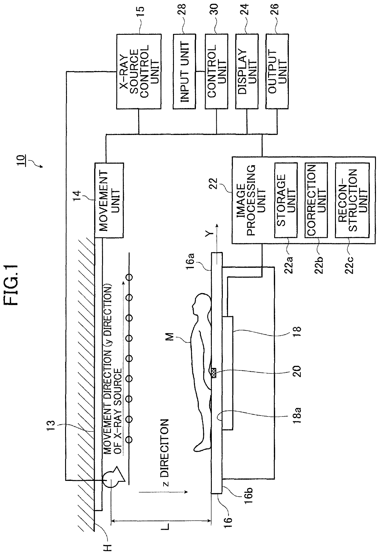
[0046]FIG. 1 is a schematic diagram illustrating an X-ray imaging device according to the present invention.

[0047]The X-ray imaging device 10 according to the first embodiment illustrated in FIG. 1 serves to image a subject M such as a human body in a tomosynthesis manner and to obtain an X-ray tomographic image of a cross section of the subject M at an arbitrary height.

[0048]The X-ray imaging device 10 can be used, for example, for tomosynthesis imaging of a decubitus posture, an upright posture, or for mammography.

[0049]The X-ray imaging device 10 can employ a built-in X-ray detector 18. When a position of a cassette does not vary before and after calibration, the X-ray imaging device 10 can employ a cassette-type X-ray detector 18.

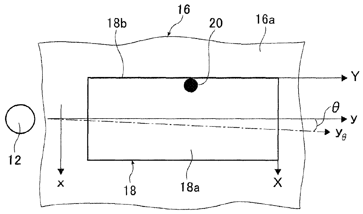
[0050]The X-ray imaging device 10 includes an overhead traveling X-ray source 12, a movement unit 14, an X-ray source control unit 15, an imaging platform 16, an X-ray detector 18, a marker 20, an image processing unit 22, a display unit 24, an output u...

second embodiment

[0112]Next, the present invention will be described below.

[0113]FIG. 7 is a schematic diagram illustrating an X-ray imaging device according to the second embodiment of the present invention. FIG. 8 is a flowchart illustrating a calibration method in the X-ray imaging device according to the second embodiment of the present invention.

[0114]In this embodiment, the same elements as elements of the first embodiment illustrated in FIGS. 1 to 5 will be referenced by the same reference numerals and detailed description thereof will not be repeated.

[0115]The X-ray imaging device 10a according to the second embodiment illustrated in FIG. 7 has the same configuration and operations as the X-ray imaging device 10 according to the first embodiment, except that a determination unit 23 is additionally provided and the operation of the image processing unit 22 and the calibration method are different in comparison with the X-ray imaging device 10 according to the first embodiment illustrated in F...


PUM


Abstract

The X-ray imaging device comprises an X-ray source that is able to move along a predetermined movement path, a movement unit configured to cause the X-ray source to move along the predetermined movement path, an imaging platform that is disposed to face the X-ray source, a flat-panel X-ray detector that is provided to the imaging platform, a marker that is disposed in the imaging platform, a control unit that causes the X-ray source to move and to capture images respectively including the marker from at least two positions, and an image processing unit that calculates a position of an image of the marker in each of the captured images and calculates a slope of a movement axis of the X-ray source with respect to the X-ray detector based on a relative relationship between positions of images of the marker.

Description

CROSS REFERENCE TO RELATED APPLICATIONS[0001]This non-provisional application is a Continuation of International Application No. PCT / JP2012 / 067336 filed on Jul. 6, 2012, which claims the benefit of Japanese Application Nos. 2011-149912 and 2011-153815 filed in Japan on Jul. 6, 2011 and Jul. 12, 2011. The entire contents of all of the above applications are hereby incorporated by reference.BACKGROUND OF THE INVENTION[0002]The present invention relates to an X-ray imaging device that captures an image in a decubitus posture, an upright posture, mammography, or the like and a calibration method therefor, and more particularly, to an X-ray imaging device that can correct a misalignment even when a movement axis of an X-ray source has the misalignment with respect to an X-ray detector, that can obtain a high-precision synthesis image (tomosynthesis image) of a cross section at a predetermined position of a subject, and that furthermore can suppress aging degradation of the misalignment a...

Claims


Application Information

Patent Timeline
Patent Type & Authority Patents(United States)
IPC IPC(8): A61B6/03G06T7/20G06T11/00A61B6/04A61B6/00A61B6/02
CPCA61B6/032A61B6/025A61B6/0492A61B6/4233A61B6/584A61B6/585A61B6/587A61B6/588G06T7/2033G06T11/005G06T2207/30204G06T2207/30241A61B6/4283A61B6/4452A61B6/4464A61B6/502G06T2207/10016G06T2207/10116G06T2207/30004G06T7/246
Inventor AKAHORI, SADATO
Owner FUJIFILM CORP
Why Eureka
Try Eureka