Stirling engine with regenerator internal to the displacer piston and integral geometry for heat transfer and fluid flow

a technology of internal displacer piston and internal regenerator, which is applied in the direction of stirling engines, machines/engines, hot gas positive displacement engine plants, etc., can solve the problems of high pumping loss, narrow process narrowness, and current stirling engine designs are subject to cracking of heater tubes and external regenerators

Active Publication Date: 2016-07-05
HOLSAPPLE ALAN CARL
View PDF9 Cites 2 Cited by
  • Summary
  • Abstract
  • Description
  • Claims
  • Application Information

AI Technical Summary

Problems solved by technology

The efficiency of the process is narrowly restricted by the efficiency of the Carnot cycle, which depends on the temperature difference between the hot and cold reservoir.
Current Stirling engine designs are subject to cracking of the heater tubes and external regenerator due to high thermal stress.
In addition, pumping losses are high.

Method used


Image

  • Stirling engine with regenerator internal to the displacer piston and integral geometry for heat transfer and fluid flow
  • Stirling engine with regenerator internal to the displacer piston and integral geometry for heat transfer and fluid flow
  • Stirling engine with regenerator internal to the displacer piston and integral geometry for heat transfer and fluid flow

Examples


Embodiment Construction

[0020]All illustrations of the drawings are for the purpose of describing selected versions of the present invention and are not intended to limit the scope of the present invention.

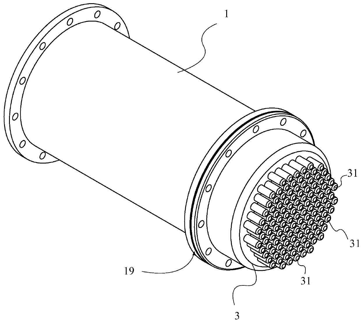
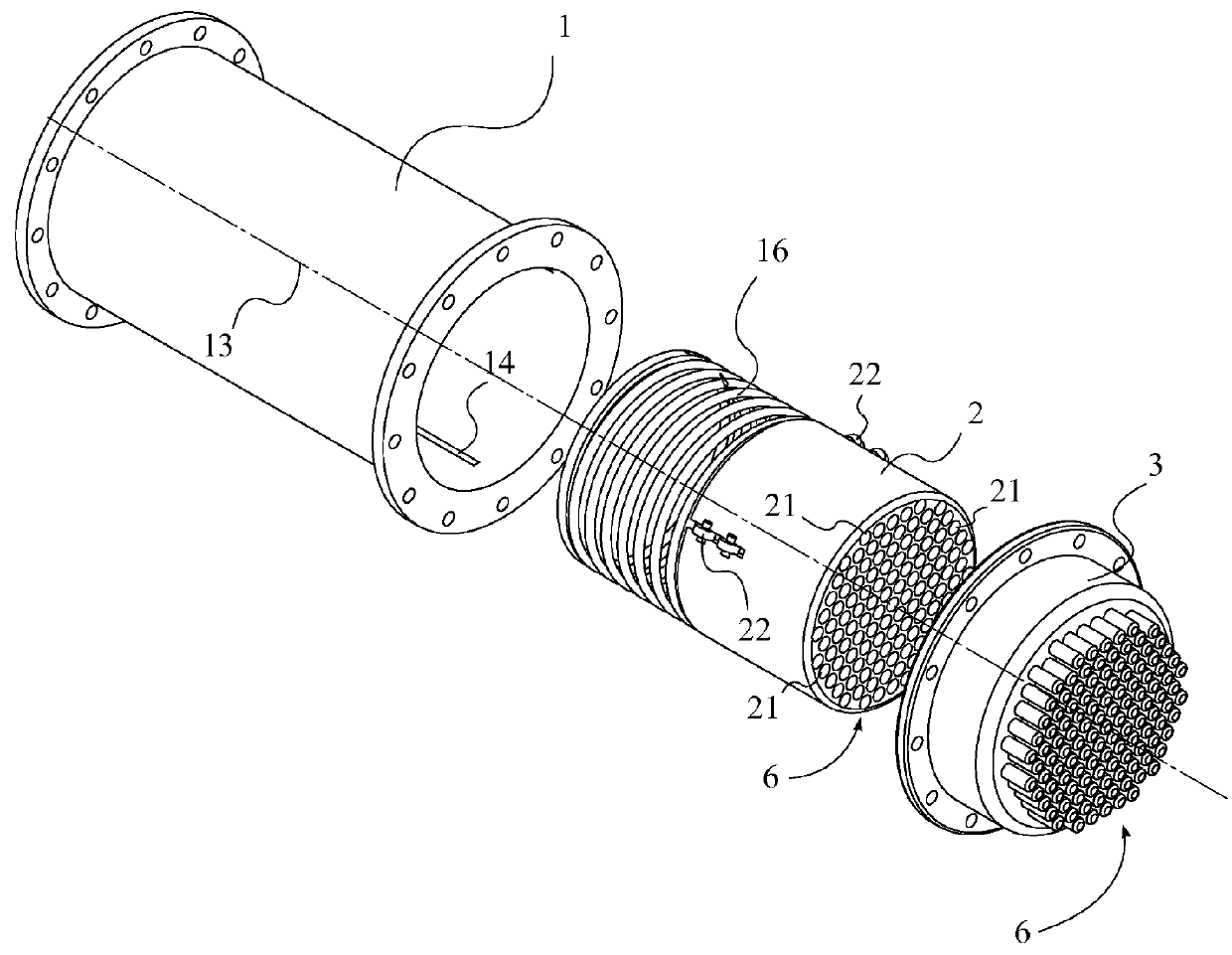
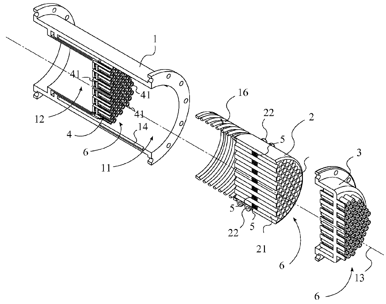
[0021]The present invention is a modification for a Stirling engine which incorporates an internal regenerator and integral geometry for improved heat transfer and fluid flow. Referring to FIGS. 1-3, in general, the present invention comprises a cylindrical housing 1, a displacer piston 2, a heater head 3, a cooling bridge 4, and a plurality of regenerator cores 5.

[0022]The cylindrical housing 1 is the substantial physical structure that contains the majority of the present invention as is typical with Stirling engines. The cylindrical housing 1 comprises a piston chamber 11 and contains a working fluid 7. The working fluid 7 is preferably a gas, such as, but not limited to, hydrogen, helium, or air. A central axis 13 centrally traverses through the cylindrical housing 1, and defines a longitudinal direc...


PUM


Abstract

A Stirling engine with internal regenerator and integral geometry for heat transfer and fluid flow has a displacer piston with a plurality of cavities that traverse through the displacer piston and are arranged in a specific cross sectional geometry. A heater head has heater fin protrusions that are also arranged in the specific cross sectional geometry, and a cooling bridge has cooler fin protrusions that are also arranged in the specific cross sectional geometry. The displacer piston alternates between the heater head and the cooling bridge, with the cavities of the piston alternately enveloping the heater protrusions and the cooling protrusions, providing more efficient heat transfer to and from the working fluid. Each cavity in the displacer also contains a regenerator core, further improving heat transfer efficiency.

Description

[0001]The current application claims a priority to the U.S. Provisional Patent application Ser. No. 61 / 675,106 filed on Jul. 24, 2012.FIELD OF THE INVENTION[0002]The present invention relates generally to power generation. More particularly, the present invention relates to a design for a more efficient Stirling engine.BACKGROUND OF THE INVENTION[0003]In the modern world, technology is everywhere. At any given time, a person probably has in their field of view an object that was manufactured at a factory. Computers, cell phones, cars, and even to a large extent the food many people eat has been part of a lengthy production line. Many things are required to produce the finished products we see today, such as manpower and infrastructure, but possibly the most important piece of modern production is power. Many different types of machines are utilized in the manufacturing and packaging of a product, and they all require mechanical work to accomplish their goal. Some machines are entire...

Claims


Application Information

Patent Timeline
Patent Type & Authority Patents(United States)
IPC IPC(8): F02G1/043F02G1/055F02G1/057
CPCF02G1/043F02G1/055F02G1/057F02G2243/02F02G2257/00F02G2280/10
Inventor HOLSAPPLE, ALAN CARL
Owner HOLSAPPLE ALAN CARL
Why Eureka
Try Eureka