Fibrous structure forming a flange and a counter-flange

Active Publication Date: 2016-07-05
SN DETUDE & DE CONSTR DE MOTEURS DAVIATION S N E C M A
View PDF7 Cites 0 Cited by
  • Summary
  • Abstract
  • Description
  • Claims
  • Application Information

AI Technical Summary

Benefits of technology

The patent describes a method of making a composite part using a fibrous structure. The main part of the fibrous structure forms the body of the composite part, while the margin forms an assembly that is folded and forms an integral part of the composite part. The margin has a flange and a counter-flange, with the second portion reinforcing the flange. The second portion has a majority of transverse fibers over longitudinal fibers, which improves its mechanical strength without limiting its ability to be folded. The technical effect is a stronger and more flexible composite part with improved mechanical strength.

Problems solved by technology

Without a counter-flange, those forces would be concentrated on the flange in the vicinity of the heads of the bolts, thereby weakening the flange.
The solution that consists in machining the regions of the flange that come into contact with the counter-flange so that the flange is a good fit with the surface of the counter-flange cannot be accepted since such machining would cut the fibers of the fibrous structure, thereby compromising the mechanical integrity of the flange, since it is the fibers that provide its mechanical strength.
These variations from one composite part to another run the risk of creating contact defects between the flange and the counter-flange, and consequently of giving rise to subsequent damage.
In addition, potential point contacts between the fibers of the flange and the metal counter-flange run the risk of giving rise to subsequent damage.
Similarly, any residual zones forming pockets of resin between the flange and the counter-flange also run the risk of giving rise to subsequent damage.
Furthermore, metal is a material that is heavy compared with composite materials, having about three times the density, thereby also presenting a drawback in the context of optimizing the weight of turbojets and turbine engines.

Method used


Image

  • Fibrous structure forming a flange and a counter-flange
  • Fibrous structure forming a flange and a counter-flange
  • Fibrous structure forming a flange and a counter-flange

Examples


Embodiment Construction

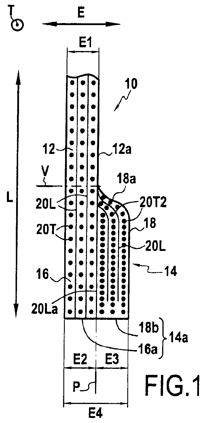
[0048]FIG. 1 shows a first embodiment of a fibrous structure 10 having a main portion 12 and a margin 14 adjacent to the main portion 12. The fibrous structure 10 is in fragmentary cross-section view with the margin 14 arranged to extend the main portion 12. In FIG. 1, arrow L designates the longitudinal direction, while arrow E represents the thickness direction. The transverse direction extends perpendicularly to FIG. 1 (i.e. perpendicularly both to the longitudinal direction and to the thickness direction) and it is represented by arrow T.

[0049]The margin 14 has a first portion 16 and a second portion 18 that are joined together. The plane P drawn in chain-dotted lines beyond the end face 12a of the main portion 12 marks the boundary between the first portion 16 and the second portion 18. It should be observed in this first embodiment that this boundary is symbolic. The second portion 18 projects from the main portion 12, and it forms a shoulder 18a. A plane V drawn in chain-dott...


PUM

PropertyMeasurementUnit
Fractionaaaaaaaaaa
Thicknessaaaaaaaaaa
Structureaaaaaaaaaa

Abstract

A fibrous structure for fabricating a composite part including a matrix reinforced by the fibrous structure, the fibrous structure being made by three-dimensional weaving and presenting a main portion and a margin adjacent to the main portion. The margin presents a thickness greater than the thickness of the main portion and the margin includes a first portion arranged in continuity with the main portion and a second portion superposed on the first portion to constitute extra thickness, the margin thus being configured to be folded towards the second portion so that the first and second portions respectively form a flange and a counter-flange for fastening the part.

Description

FIELD OF THE INVENTION[0001]The present invention relates to a fibrous structure, generally referred to as a preform, for use in fabricating a composite part that has a flange and a counter-flange, both the flange and the counter-flange being made from the fibrous structure. In particular, the invention relates to a fibrous structure for fabricating a part for a turbine engine or a turbojet.BACKGROUND OF THE INVENTION[0002]In conventional mechanical structures, parts are often connected together using flanges and counter-flanges. As a general rule, a flange is a portion extending at an angle from the end of a part along all or part of its circumference, and used for joining said part to another part by bolting, the bolts passing through the flange. A counter-flange is a reinforcing part that presents the same general shape as the flange and that is disposed between the heads of the bolts and the flange. The function of the counter-flange is to distribute the forces that hold the par...

Claims


Application Information

Patent Timeline
IPC IPC(8): F04D29/54B29B11/16B29C70/22
CPCB29B11/16B29C70/24Y10T428/1362Y10T428/24488B29C70/222F04D29/54
Inventor OLIVIER, LOIC
Owner SN DETUDE & DE CONSTR DE MOTEURS DAVIATION S N E C M A
Why Eureka
Try Eureka