Evaluation method and evaluation system for impact force of laser irradiation during laser peening and laser peening method and laser peening system

a laser peening and laser peening technology, which is applied in the direction of force/torque/work measurement, heat treatment process control, and solids analysis using sonic/ultrasonic/infrasonic waves. it is difficult to make an x-ray incident on a complicated-shaped object, and it is difficult to evaluate the degree of force applied to the surface of the workpiece during shot peening processing

Active Publication Date: 2016-07-05
SINTOKOGIO LTD
View PDF13 Cites 5 Cited by
  • Summary
  • Abstract
  • Description
  • Claims
  • Application Information

AI Technical Summary

Benefits of technology

[0041]As explained above, according to the various aspects and embodiments of the present invention, an evaluation method for appropriately evaluating a force applied to the surface of a workpiece member during laser peening and an evaluation system for the evaluation method are provided. A laser peening method and a laser peening system for irradiating a laser on the basis of knowledge obtained by the evaluation method and the evaluation system are provided.

Problems solved by technology

However, although the residual stress on a material surface can be measured in a non-destructive manner by the X-ray diffraction method, since a measurement region of a workpiece member has to be shaved when it is desired to obtain a residual stress distribution on the inside, a residual stress distribution of an actual product cannot be measured without breaking the product.
There are many limitations in an evaluation method because it is difficult to make an X ray incident on a complicated-shaped object such as a gear.
When shot peening intensity is evaluated using the almen strip, it is impossible to evaluate which degree of force is applied to the surface of the workpiece member during shot peening processing.

Method used


Image

  • Evaluation method and evaluation system for impact force of laser irradiation during laser peening and laser peening method and laser peening system
  • Evaluation method and evaluation system for impact force of laser irradiation during laser peening and laser peening method and laser peening system
  • Evaluation method and evaluation system for impact force of laser irradiation during laser peening and laser peening method and laser peening system

Examples


examples

Measurement of an AE waveform

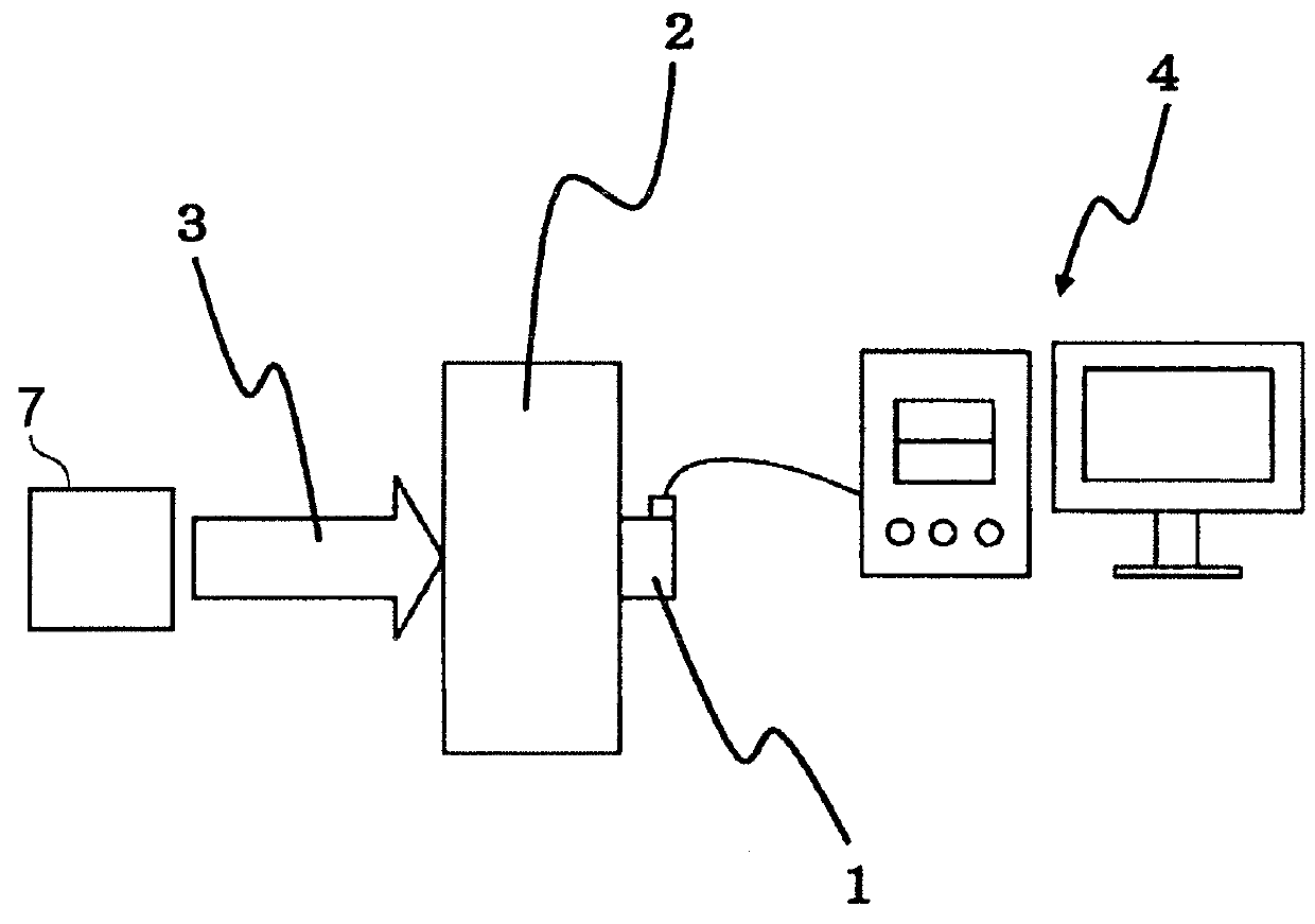
[0111]An AE waveform was measured. As the workpiece member 2 on which a laser is irradiated, workpiece members having different thicknesses and of different materials were used. The workpiece member 2 had plane width of 35 mm×35 mm. Three kinds of workpiece members having thicknesses of 5 mm, 10 mm, and 20 mm were prepared. Two kinds of workpiece members of materials A7075 (Japanese Industrial Standards) and S50C (Japanese Industrial Standards) were prepared. In other words, six pieces of workpiece members 2 were prepared in total.

[0112]As the laser source 7, a Q switch Nd-YAG laser was used. Main specifications of the laser source 7 are shown in Table 1.

[0113]

TABLE 1Maximum pulse energyWavelengthPulse widthSpot area500 mJ532 nm7.5 ns1.09 × 10−3 cm2

[0114]Energy of the laser irradiated on the workpiece member 2 was adjusted by changing an angle of a polarization plate. Energy density of the laser was multiplied 23 times by a condenser lens. The laser was ...


PUM

PropertyMeasurementUnit
wavelengthaaaaaaaaaa
time resolutionaaaaaaaaaa

Abstract

A method of evaluating impact force input to a workpiece member with a laser irradiated in laser peening processing is provided. This evaluation method includes a signal acquiring step, an input function calculating step, and an evaluating step. In the signal acquiring step, a detected waveform is acquired. The detected waveform is output during the laser peening processing by an AE sensor that detects an elastic wave generated in the workpiece member. In the input function calculating step, an input function I(t) by laser irradiation is calculated. In the evaluating step, impact force is evaluated using the input function I(t) by the laser irradiation.

Description

TECHNICAL FIELD[0001]The present invention relates to an evaluation method and an evaluation system for impact force of laser irradiation during laser peening and a laser peening method and a laser peening system. More specifically, the present invention relates to a method of evaluating, using a result obtained by using an AE (Acoustic Emission) sensor, impact force input to a workpiece member (material) during laser peening and a laser peening method and a laser peening system for irradiating a laser on the basis of knowledge obtained by the evaluation method and an evaluation system.BACKGROUND ART[0002]Conventionally, shot peening intensity has been evaluated using an arc height value obtained by using an almen strip. However, in quality management of the present state, in some cases, the shot peening intensity is managed using a peak value and depth of residual stress rather than the arc height value. This residual stress can be measured by an X-ray diffraction method (see, for ...

Claims


Application Information

Patent Timeline
Patent Type & Authority Patents(United States)
IPC IPC(8): G01L5/00G06F17/00G01N29/44G01N29/24G01N29/14G01N29/04C21D11/00B23K26/03B23K26/00C21D10/00C21D9/32C21D7/06
CPCG01L5/0052B23K26/0069B23K26/03C21D10/00C21D10/005C21D11/00G01N29/045G01N29/14G01N29/2418G01N29/4472G06F17/00C21D7/06C21D9/32B23K26/356
Inventor ENOKI, MANABUMATSUI, AKINORIKOBAYASHI, YUJI
Owner SINTOKOGIO LTD
Why Eureka
Try Eureka