Harsh environment pressure compensator for inline cable termination

a compensator and inline cable technology, applied in the direction of coupling device connection, optical elements, instruments, etc., can solve the problems of not being as durable as metallic materials, the shell and housing of prior art devices are typically very thick to withstand collapsing, etc., to reduce the amount of compressible gas contained, simplify the exterior shape and assembly, and reduce the effect of outside pressur

Active Publication Date: 2016-07-12
TELEDYNE INSTR INC
View PDF11 Cites 5 Cited by
  • Summary
  • Abstract
  • Description
  • Claims
  • Application Information

AI Technical Summary

Benefits of technology

[0018]Prior art methods to prevent damage under pressure include filling voids with pressure compensating fluids, which are nearly incompressible, in order to minimize the amount of compressible gas contained within. Adding a pressure compensating fluid to a void or cavity in the housing of a subsea device lessens the compressive effects of the outside pressures on the housing of the device. However, fluids are marginally compressible, and therefore shells and housings in prior art devices are typically very thick to withstand collapsing as the device is not truly pressure compensated.
[0019]The present invention comprises an inline pressure compensator that provides for pressure normalization of interior chambers in termination assemblies. The present invention has a rigid inline configuration to simplify exterior shape and assembly. The inline configuration also provides for coaxial pressure compensation without movement of internal termination elements.
[0021]In order to insure that the shell of the termination does not collapse due to the volume shrinkage of pressure-compensating fluid as a result of high hydrostatic pressures, the termination housing of prior art devices is typically designed to have a thick exterior. The interior cavity of the present invention is fully pressure-compensated and it is therefore no longer necessary to implement a thick shell. The fully pressure-compensated, thinner shelled termination assembly of the present invention has a reduced overall size and utilizes less material than prior art designs. The fully pressure-compensated interior of the present invention also reduces the possibility of stress cracks developing in the termination housing, through which water could possibly ingress and cause a failure to occur.
[0023]Furthermore, prior art pressure compensator designs have used such devices as pistons, bladders, and metallic bellows that are fixed transversely to the subsea device they are neutralizing. Such prior art assemblies occupy more space than necessary to account for the additional exterior fixtures as well as the potential range of expansion of the compensation device when experiencing changes in pressure. The rigid inline pressure compensator of the present invention minimizes the space occupied by the termination assembly itself and, with the immobility of the pressure compensator structure, eliminates additional space required for pressure compensation expansion. The inline design of the present invention provides increased reliability and simplifies the assembly process by implementing a stack-up procedure compared to the additional attachment of posterior parts required by the prior art devices.

Problems solved by technology

However, fluids are marginally compressible, and therefore shells and housings in prior art devices are typically very thick to withstand collapsing as the device is not truly pressure compensated.
In prior pressure compensation designs have used devices such as rubber bladders and diaphragms to manipulate volumes within subsea devices, however a problem with such designs is that rubber and like materials are not as durable as metallic material, which can withstand a design life of 20 to 30 years.

Method used


Image

  • Harsh environment pressure compensator for inline cable termination
  • Harsh environment pressure compensator for inline cable termination
  • Harsh environment pressure compensator for inline cable termination

Examples


Embodiment Construction

[0035]The present invention and system will now be described in more detail with reference to exemplary embodiments as shown in the accompanying drawings. While the present invention and system is described herein with reference to the exemplary embodiments, it should be understood that the present invention and system is not limited to such exemplary embodiments. Those possessing ordinary skill in the art and having access to the teachings herein will recognize additional implementations, modifications, and embodiments as well as other applications for use of the invention and system, which are fully contemplated herein as within the scope of the present invention and system as disclosed and claimed herein, and with respect to which the present invention and system could be of significant utility.

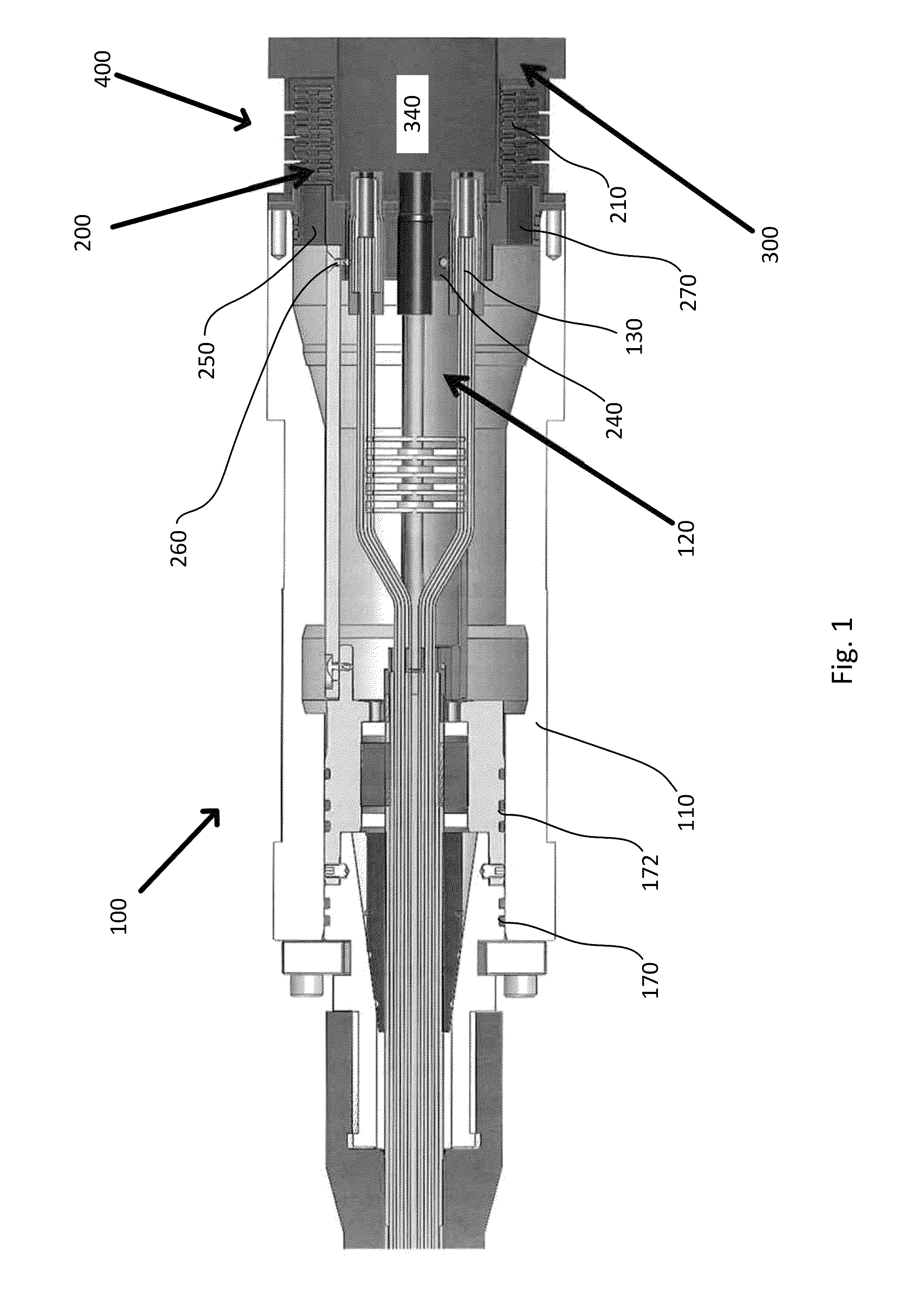
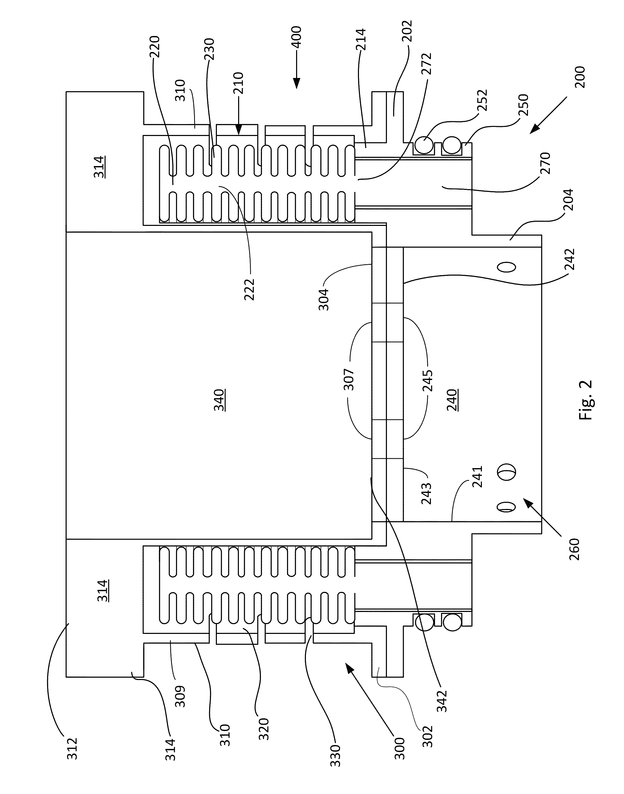
[0036]The present invention generally relates to an inline pressure compensator that compensates for volumetric changes within Field-Assembled Cable Termination (FACT) structures when expo...


PUM


Abstract

The present invention generally relates to an inline pressure compensator that compensates for volumetric changes within Field-Assembled Cable Termination (FACT) structures when exposed to high pressures and extreme subsea depths by transferring a pressure compensating fluid into the internal cavity of the FACT. The present invention may comprise a flexible internal component and an outer shell-like component. The inner component may comprise two concentric rings of edge-welded bellows that are joined together and wrapped around inner components of the termination or of the inner portion of the outer component. The inner void in the bellows may be filled with pressure-compensating fluid. The pressure compensating fluid diffuses directly into the fluid-filled cavity of the termination assembly. The exterior component may comprise a housing adapted to protect the interior bellows component and provide for seawater to fill the space around the periphery of the bellows arrangement.

Description

FIELD OF THE INVENTION[0001]The present invention generally relates to subsea connector assemblies and more particularly to connector assemblies of the pressure compensated type. The present invention also relates to compensating pressure in volumes of fluid having been compressed or decompressed by changes in external hydrostatic pressure.BACKGROUND OF THE INVENTION[0002]In various undersea operations, especially in connection with undersea oil or gas wells, operational and monitoring equipment requires electrical and / or optical connection to various equipment. Such equipment can for instance be a flow meter for monitoring the flow of hydrocarbons in a pipe, a temperature gauge, a pressure gauge, etc. Such connections may also be needed in order to actively control equipment such as valves, or control devices such as microcontrollers.[0003]In offshore drilling and production operations, equipment are often subjected to harsh conditions thousands of feet under the sea surface with w...

Claims


Application Information

Patent Timeline
Patent Type & Authority Patents(United States)
IPC IPC(8): E21B17/02E21B7/12
CPCE21B17/028G02B6/4428H01R13/523H02G15/003H02G15/007H02G15/14H02G15/22
Inventor MCCLEARY, ALANKRETSCHMAR, JUSTINMISHLER, KALEY
Owner TELEDYNE INSTR INC
Why Eureka
Try Eureka