Check patentability & draft patents in minutes with Patsnap Eureka AI!

Engine with a variable volume chamber

a variable-volume chamber and engine technology, applied in the field of engines, can solve the problems of implementing a relatively heavy and complex mechanical and kinematic chain, affecting reducing the efficiency of the engine, so as to achieve the effect of simple design and easy manufacturing

Active Publication Date: 2016-07-12
DAOUK ANTAR
View PDF11 Cites 1 Cited by
  • Summary
  • Abstract
  • Description
  • Claims
  • Application Information

AI Technical Summary

Benefits of technology

This patent aims to create a new engine that is small, durable, easy to manufacture, and works on simple mechanical principles. Additionally, it should minimize vibration and noise, have significant intake and exhaust sections, and use a minimum number of parts.

Problems solved by technology

This known engine architecture generally gives satisfaction, but nevertheless presents serious drawbacks.
In particular, these known engines implement a relatively heavy and complex mechanical and kinematic chain for transmitting and returning force between the pistons and the output shaft.
This obviously constitutes a potential source of failure and of loss of energy efficiency, and is not in line with the trend toward increased reliability or toward reducing cost price.
Furthermore, these known engines implement a large number of moving parts, which represents a significant moving mass, which is also likely to bring about effectiveness and reliability problems.
These known engines are also relatively heavy and bulky, so that their installation within a vehicle, and notably within a motor vehicle of the individual car type, may prove problematic, notably with regard to the correct positioning of the center of gravity of the engine in the vehicle.
Finally, the efficiency of these known engines is not optimal in the various usage modes of the engine, which leads to fuel overconsumption.
The known variable compression engines do, however, also suffer from the drawbacks mentioned above with regard to the conventional explosion engines.
These drawbacks are even emphasized since the production of a variable compression ratio chamber is generally obtained, in the known VCR engines, by the implementation of complex mechanical systems for controlling the travel of the pistons, which not only increase the weight of the engine and affect its reliability, but are also likely to lead to the appearance of undesirable vibratory and acoustic phenomena.
In addition, industrial engineering of these known VCR engines is difficult, which results in a significant increase in the cost price of the engine.

Method used


Image

  • Engine with a variable volume chamber
  • Engine with a variable volume chamber
  • Engine with a variable volume chamber

Examples


Embodiment Construction

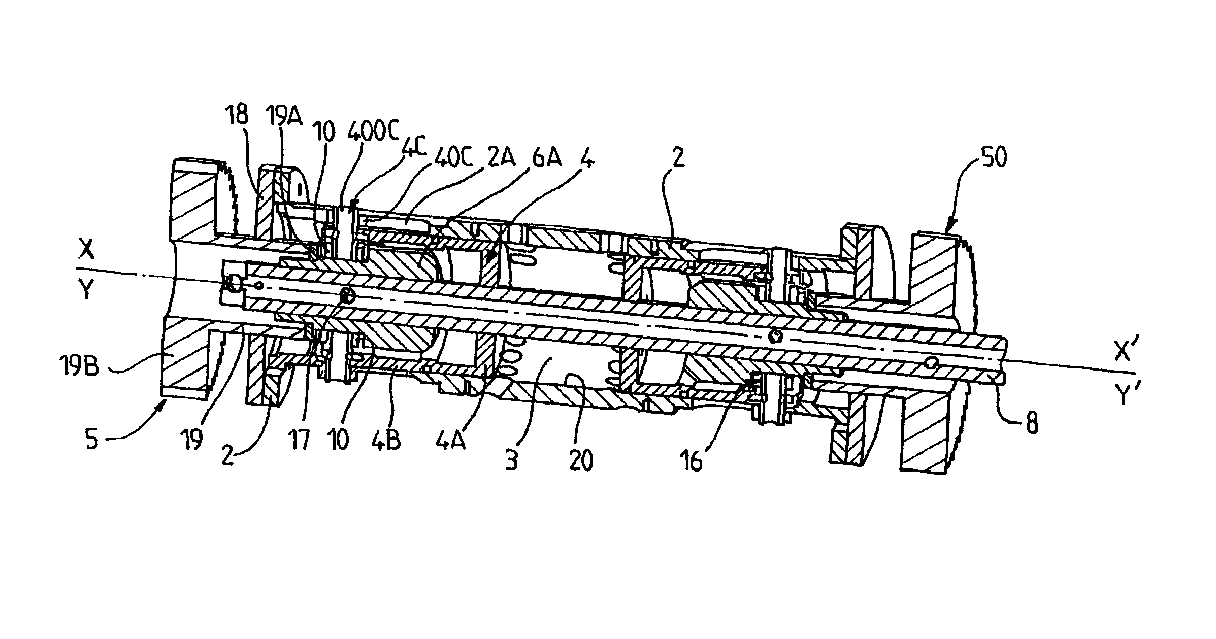
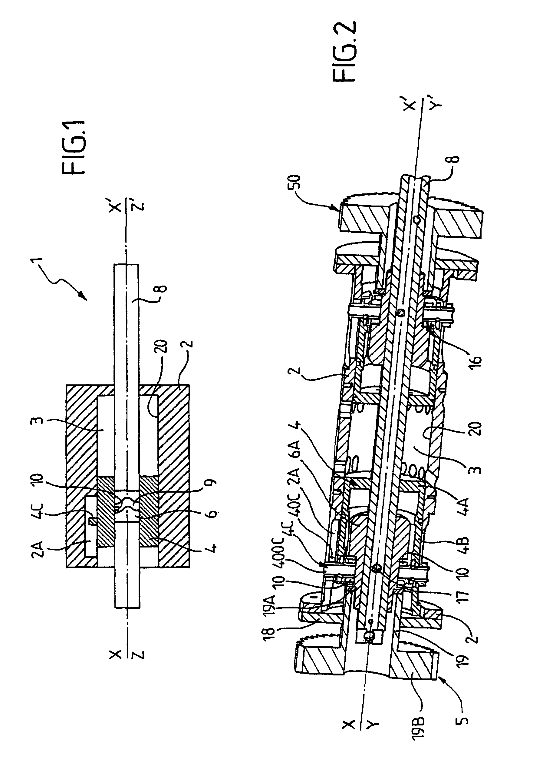
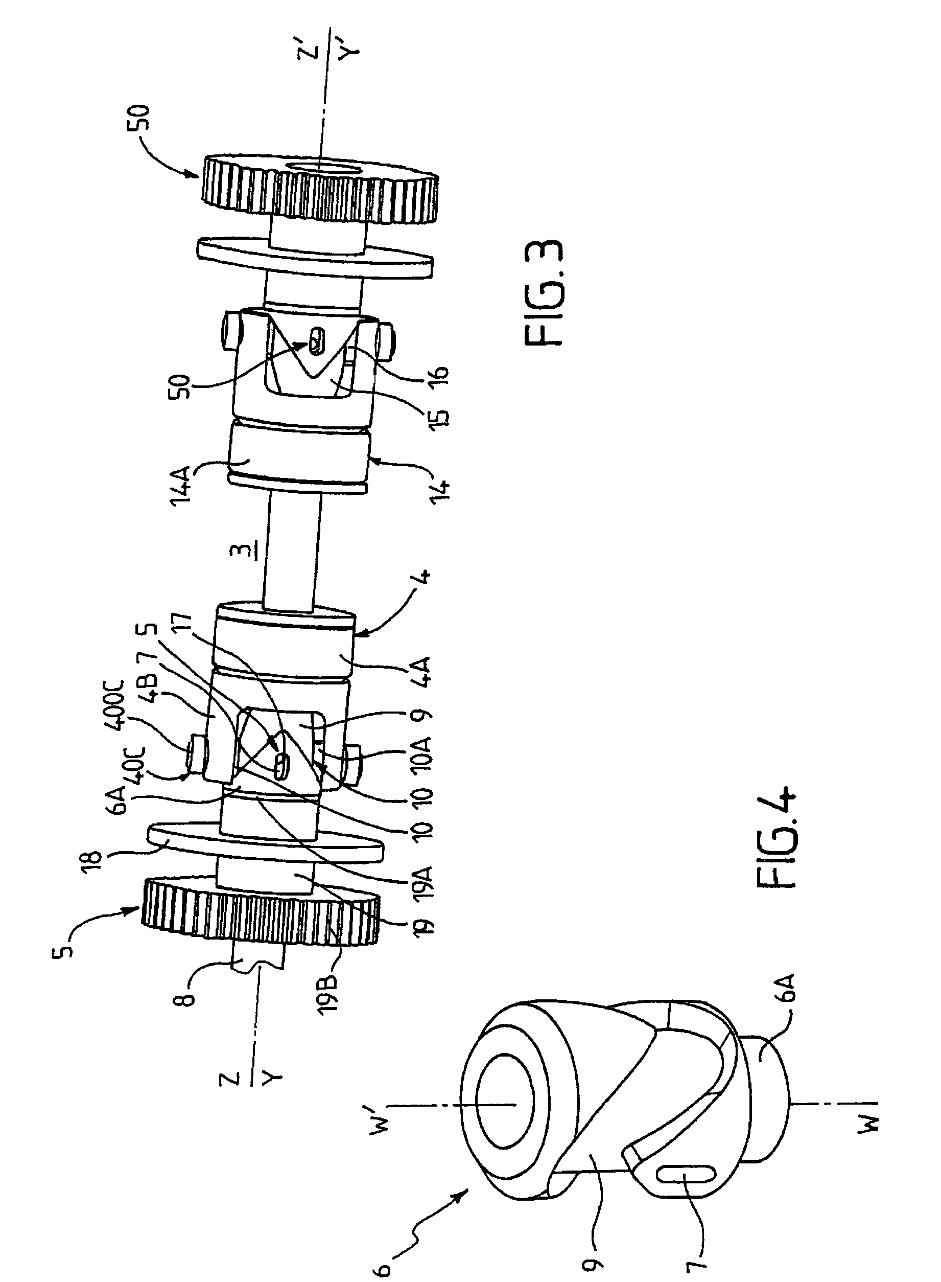
[0032]The invention relates to an engine, that is to say a device capable of supplying mechanical work that can be used notably to propel a vehicle, and for example a motor vehicle, a motorbike, an aircraft or a boat, or even to operate a machine (machine-tool, public works machine, agricultural machine, pump, compressor) or an energy conversion device, such as a generator.

[0033]The engine 1 according to the invention preferably constitutes an internal combustion engine (“explosion engine”), that is to say, an engine capable of producing mechanical energy from the combustion within it of a working fluid containing a fuel, and for example a hydrocarbon-based fuel such as gasoline. The invention is not, however, limited to combustion engines and may relate to an engine whose operation is not based on the combustion of fuel, as is the case, for example, with compressed air engines.

[0034]The engine 1 according to the invention comprises at least the following three components: a cylinde...


PUM


Abstract

The invention relates to an engine including: —a cylinder that contributes to define a chamber (3), —a first piston (4), said first piston (4) and cylinder are subjected to a first relative back-and-forth motion, —an output shaft (8), —a second piston (14), said second piston (4) and cylinder are subjected to a second relative back-and-forth motion, said output shaft (8) mounted coaxially to said pistons (4, 14), —a first means for converting (5) said first relative back-and-forth movement into rotational motion of the output shaft (8), including, on one side, a first corrugated guide track (9) and, on the other side, a first guide element (10) designed to move along said guide track (9), —a first adjustment member (5) to position the first guide track (9).

Description

[0001]This application is a §371 national stage of PCT International Application No. PCT / FR2009 / 050443, filed Mar. 17, 2009, claiming priority of French Patent Application No. 0801437, filed Mar. 17, 2008, the contents of all of which are hereby incorporated by reference into this application.TECHNICAL FIELD[0002]The present invention relates to the general technical field of engines, and in particular engines whose operation is based on the variation of the volume of a chamber (for example, by compression and expansion of a working fluid within the chamber), such engines supplying a mechanical energy that can be used, for example, to propel vehicles (such as automobiles, motorbikes, aircraft or boats), to drive machines (industrial or agricultural), or even to supply mechanical energy to energy conversion devices, of the electricity generator set type.[0003]The invention relates more specifically to an engine comprising at least the following three components:[0004]a cylinder which...

Claims


Application Information

Patent Timeline
Patent Type & Authority Patents(United States)
IPC IPC(8): F01B7/00F01B7/04F01B7/02F01B3/04F01B9/06F02B75/28F02B75/04
CPCF01B3/04F01B7/00F01B7/02F01B7/04F01B9/06F02B75/045F02B75/282
Inventor DAOUK, ANTAR
Owner DAOUK ANTAR
Features
  • R&D
  • Intellectual Property
  • Life Sciences
  • Materials
  • Tech Scout
  • Unparalleled Data Quality
  • Higher Quality Content
  • 60% Fewer Hallucinations
Learn More