Ion selection method in ion trap and ion trap system

a technology of ion trap and ion trap, which is applied in the direction of energy spectrometers, electric discharge tubes, particle separator tubes, etc., can solve the problems of critical and unavoidable problems, significantly reducing the throughput of analysis, and requiring a considerable amount of time, so as to improve the throughput of msn analysis and reduce the time consuming. , the effect of short time period

Active Publication Date: 2016-07-19
SHIMADZU CORP
View PDF36 Cites 4 Cited by
  • Summary
  • Abstract
  • Description
  • Claims
  • Application Information

AI Technical Summary

Benefits of technology

[0045]With the ion selection method and the ion trap system according to the present invention, it is possible to conduct an ion selection process, such as precursor isolation, so as to leave a target ion or ion group within an ion trap with high resolving power and in a short period of time. As a result, for example, the throughput of an MSn analysis can be improved in a mass spectrometer using an ion trap.

Problems solved by technology

However, there is the problem that a considerable amount of time is required if a method like the one described in Non Patent Literature 1 is used for the precursor isolation of a specific ion with high mass-separating power.
Accordingly, consuming several hundreds of milliseconds for only process (B) will significantly lower the throughput of the analysis.
In recent years, improving the throughput of an analysis has been extremely important in the field of mass spectrometry, and time reduction of the precursor isolation in the DIT is a critical and unavoidable problem.
Although such a precursor isolation technique can be used as the aforementioned rough isolation, it is difficult to use this technique as the high-resolution precursor isolation which follows the rough isolation, since its resolving power is insufficient.

Method used


Image

  • Ion selection method in ion trap and ion trap system
  • Ion selection method in ion trap and ion trap system
  • Ion selection method in ion trap and ion trap system

Examples


Embodiment Construction

First Ion-Selection Method

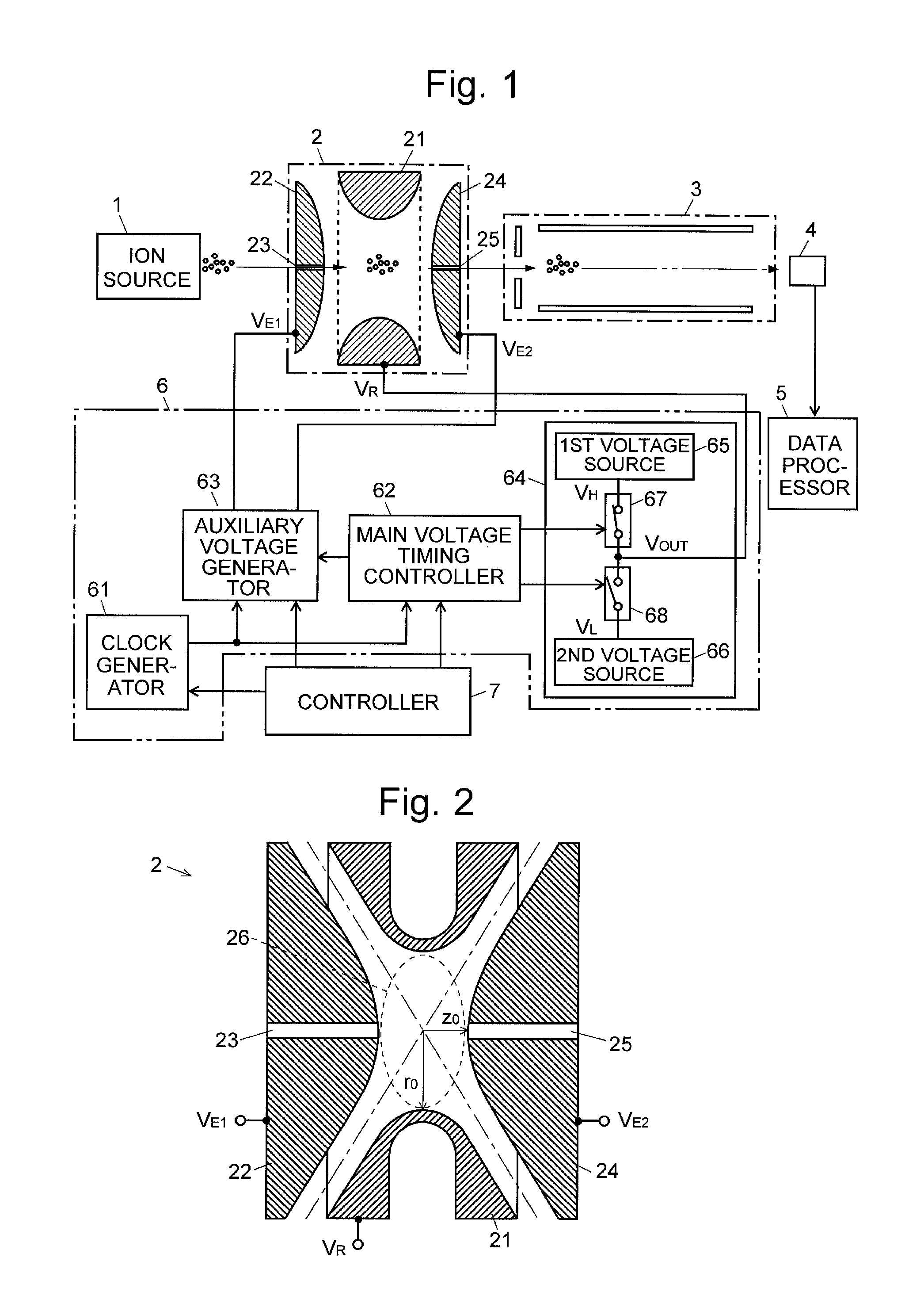
[0064]Initially, one technique of the ion selection method according to the present invention is described with reference to the drawings. It is hereinafter assumed that a three-dimensional quadrupole ion trap 2 as shown in FIG. 2 is used as the ion trap. That is to say, this ion trap 2 includes a ring electrode 21 and a pair of end-cap electrodes 22 and 24 arranged to face each other across the ring electrode 21. The two end-cap electrodes 22 and 24 have, at their respective centers, an ion injection hole 23 and an ion ejection hole 25, both holes approximately lying on the same straight line. This straight line passing through the centers of the ion injection hole 23 and the ion ejection hole 25 is the z axis of the ion trap 2. An axis which is perpendicular to the z axis and which extends in the radial direction of the ring electrode 21 is the r axis of the ion trap 2.

[0065]As is generally known, in such an ion trap 2, it is possible to promote, by reson...


PUM


Abstract

Provided is an ion selection method capable of isolating and leaving a target ion in an ion trap within a short period of time and with high separating power. In a digital ion trap, after ions over a wide range of m / z near a target ion are selectively retained by rough isolation using an FNF signal or the like (S11), unnecessary ions on a low-mass side are removed with high separating power by changing the duty ratio of a rectangular voltage (S12). Furthermore, unnecessary ions on a high-mass side are removed with high separating power by resonant excitation discharge (S13).

Description

CROSS REFERENCE TO RELATED APPLICATIONS[0001]This application is a National Stage of International Application No. PCT / JP2013 / 074134, filed on Sep. 6, 2013, which claims priority from Japanese Patent Application No. 2012-198396, filed on Sep. 10, 2012, the contents of all of which are incorporated herein by reference in their entirety.TECHNICAL FIELD[0002]The present invention relates to an ion selection method for selectively leaving a specific kind of ion within an ion trap which captures ions by an effect of a radio-frequency electric field, as well as an ion trap system for carrying out this ion selection method. For example, the ion trap system can be used in an ion-trap time-of-flight mass spectrometer in which the ion trap system is combined with a time-of-flight mass spectrometer or an ion-trap mass spectrometer which performs mass spectrometry using the mass-separating function of the ion trap itself.BACKGROUND ART[0003]In an ion-trap time-of-flight mass spectrometer, ion-t...

Claims


Application Information

Patent Timeline
Patent Type & Authority Patents(United States)
IPC IPC(8): H01J49/42H01J49/44
CPCH01J49/424H01J49/427H01J49/4285
Inventor KODERA, KEIHAZAMA, MAKOTO
Owner SHIMADZU CORP
Why Eureka
Try Eureka