Composite carbon fibers
a technology of carbon fibers and composite fibers, which is applied in the field of composite fibers, can solve the problems of large amount of carbon nanofibers that needs to be added, difficult to achieve the state in which each of the carbon nanotubes is untangled, and the electric conductivity imparting effect may not be as good as expected, etc., and achieves excellent effect, high aspect ratio, and easy dispersion
- Summary
- Abstract
- Description
- Claims
- Application Information
AI Technical Summary
Benefits of technology
Problems solved by technology
Method used
Image
Examples
manufacturing example 1
Catalyst Preparation
[0084]To prepare a support, aluminium hydroxide (Showa Denko K.K., HIGILITE® M-43 [registered trademark]) was heat-treated at 850° C. for 2 hours under the atmosphere in which air was flowing.
[0085]To a 300 ml tall beaker, 50 g of pure water were added, and then 4.0 g of the support were added and dispersed to prepare support slurry.
[0086]To a 50 ml beaker, 16.6 g of pure water were added and then 0.32 g of hexaammonium heptamolybdate tetrahydrate (Junsei Chemical Co., Ltd.) was added and dissolved. Subsequently, 7.23 g of iron (III) nitrate nonahydrate (Kanto Chemical Co., Inc.) were added and dissolved to prepare a catalyst solution.
[0087]Further, to another 50 ml beaker, 32.7 g of pure water were added, and then 8.2 g of ammonium carbonate (Kanto Chemical Co., Inc.) were added and dissolved to prepare a pH adjustment solution.
[0088]A stirring bar was placed in the tall beaker containing the support slurry, and stirred on a magnetic stirrer. Each of the catalys...
manufacturing example 2
Synthesis of the Multi-Walled Carbon Nanotubes: MWCNT
[0089]On a quartz boat, placed was 1.0 g of the catalysts obtained in Manufacturing Example 1. This was placed at the center of a horizontal tubular furnace (a quartz tube: inside diameter: 50 mm, length: 1500 mm, soaking zone: 600 mm). The horizontal tubular furnace was heated to 680° C. in 30 minutes with nitrogen gas flowed therethrough at 500 ml / min. Then, the nitrogen gas supply was stopped, and a mixed gas of ethylene and hydrogen (the concentration of ethylene: 50% by volume) was then supplied at 2000 ml / min, and allowed to react for 20 minutes to synthesize multi-walled carbon nanotubes. The mixed gas supply was stopped, and then nitrogen gas was supplied. After cooled down to room temperature, the multi-walled carbon nanotubes were taken out from the furnace.
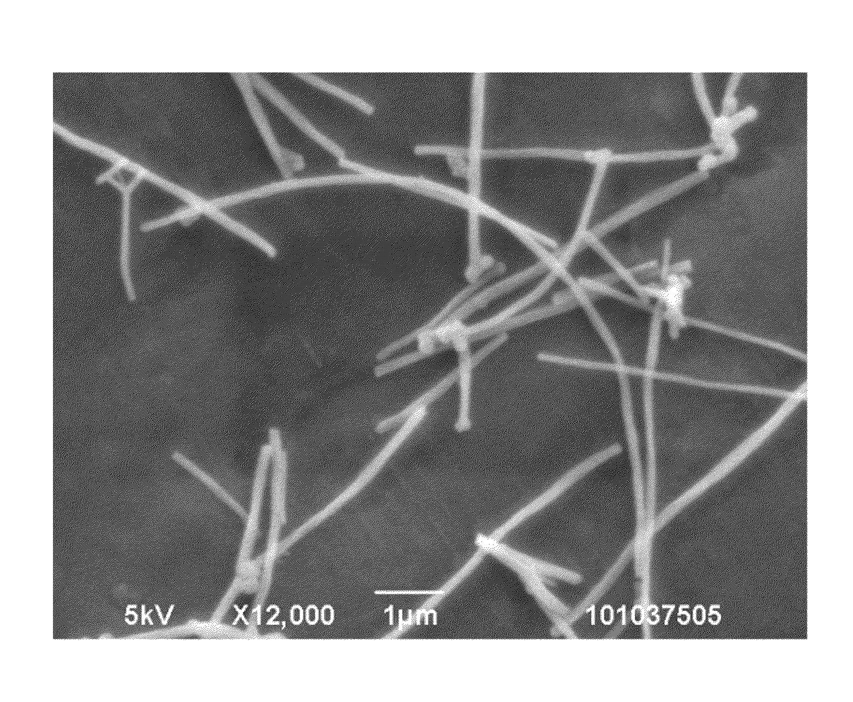
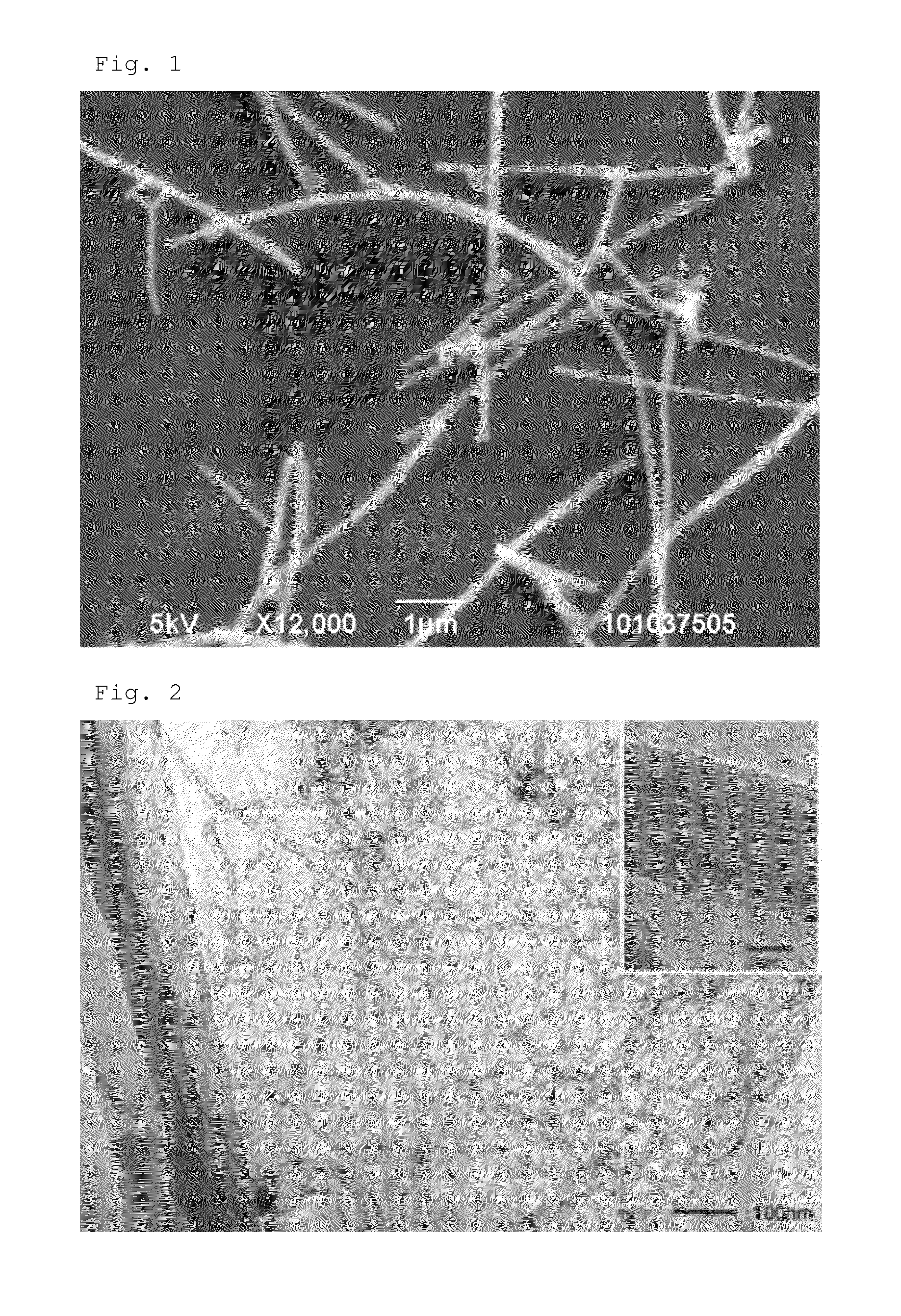
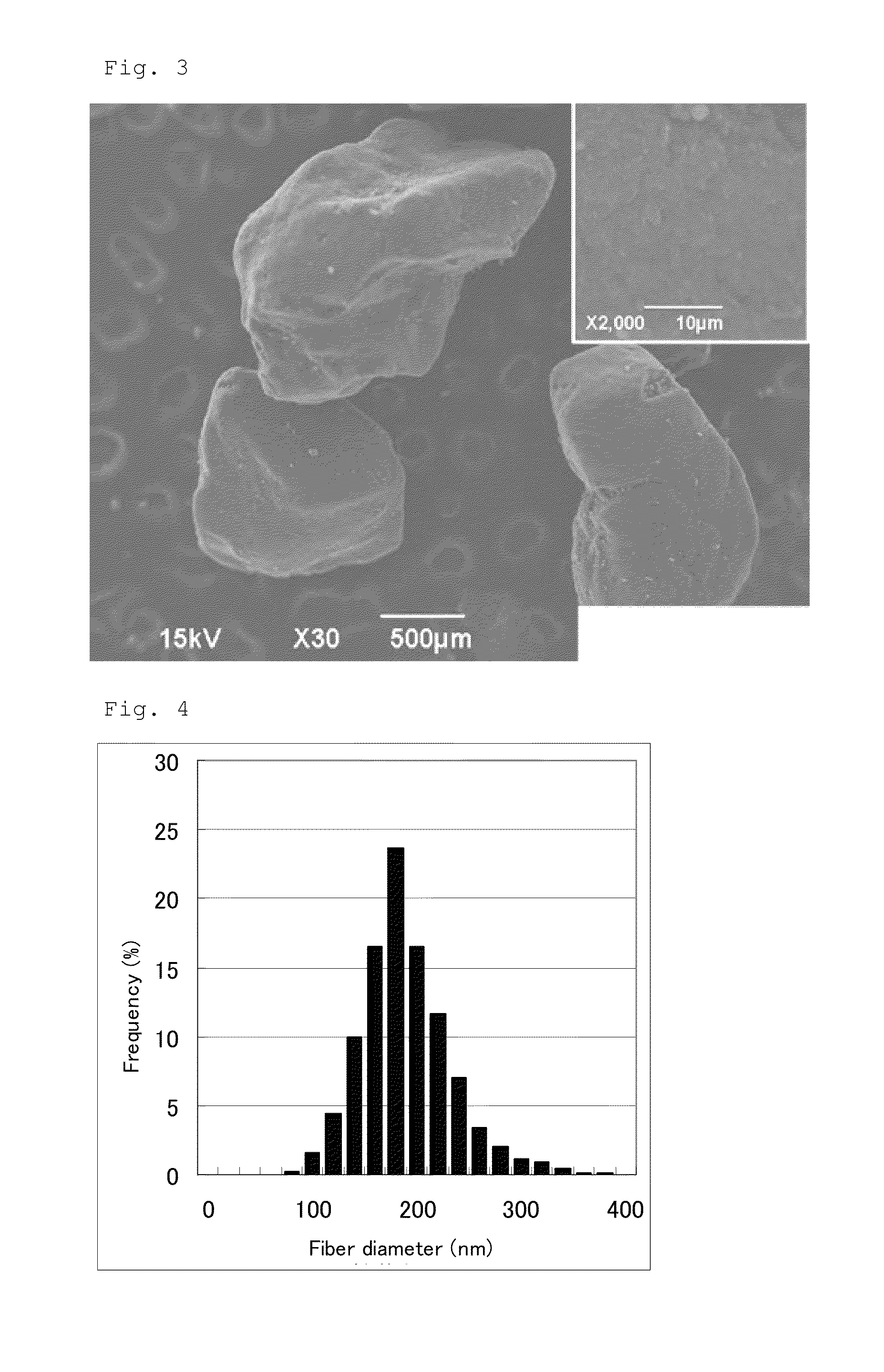
[0090]Fiber dimensions and powder properties are shown in Table 1. A transmission electron microscope image is shown in FIG. 2, a scanning electron microscope image o...
manufacturing example 3
Pulverization of the Multi-Walled Carbon Nanotubes: Pulverized MWCNT
[0091]The multi-walled carbon nanotubes synthesized in Manufacturing Example 2 were fed to a jet mill STJ-200 from Seishin Enterprise Co., Ltd. at 6 kg / h for pulverization under the conditions of a pusher nozzle pressure of 0.64 MPa and a grinding nozzle pressure of 0.60 MPa. The 50% particle diameter D50 in the volume based accumulative particle size distribution of the aggregates was 10 μm.
[0092]Fiber dimensions and powder properties are shown in Table 1. The results from thermal analysis are shown in FIG. 6.
PUM
| Property | Measurement | Unit |
|---|---|---|
| diameter | aaaaa | aaaaa |
| diameter | aaaaa | aaaaa |
| primary particle diameter | aaaaa | aaaaa |
Abstract
Description
Claims
Application Information
 - R&D
- Intellectual Property
- Life Sciences
- Materials
- Tech Scout
- Unparalleled Data Quality
- Higher Quality Content
- 60% Fewer Hallucinations
Browse by: Latest US Patents, China's latest patents, Technical Efficacy Thesaurus, Application Domain, Technology Topic, Popular Technical Reports.
© 2025 PatSnap. All rights reserved.Legal|Privacy policy|Modern Slavery Act Transparency Statement|Sitemap|About US| Contact US: help@patsnap.com


