Wireless transmission synchronization using a power line signal

a technology of power line signal and wireless transmission, which is applied in the direction of power distribution line transmission, instruments, data switching details, etc., can solve the problems of shortening the life of the fci, disproportionate amount, and complicated troubleshooting process

Inactive Publication Date: 2016-08-09
THOMAS & BETTS INT INC
View PDF35 Cites 127 Cited by
  • Summary
  • Abstract
  • Description
  • Claims
  • Application Information

AI Technical Summary

Problems solved by technology

However, in some instances, resettable FCIs may clear the fault indication prior to it being observed by the technician, thus complicating the trouble-shooting process.
For example, synchronizing the transmissions of multiple FCIs along a power line can be time-consuming and may draw a disproportionate amount of on-board power, thus potentially shortening the life span of the FCI.

Method used


Image

  • Wireless transmission synchronization using a power line signal
  • Wireless transmission synchronization using a power line signal
  • Wireless transmission synchronization using a power line signal

Examples


Embodiment Construction

[0012]The following detailed description refers to the accompanying drawings. The same reference numbers in different drawings may identify the same or similar elements.

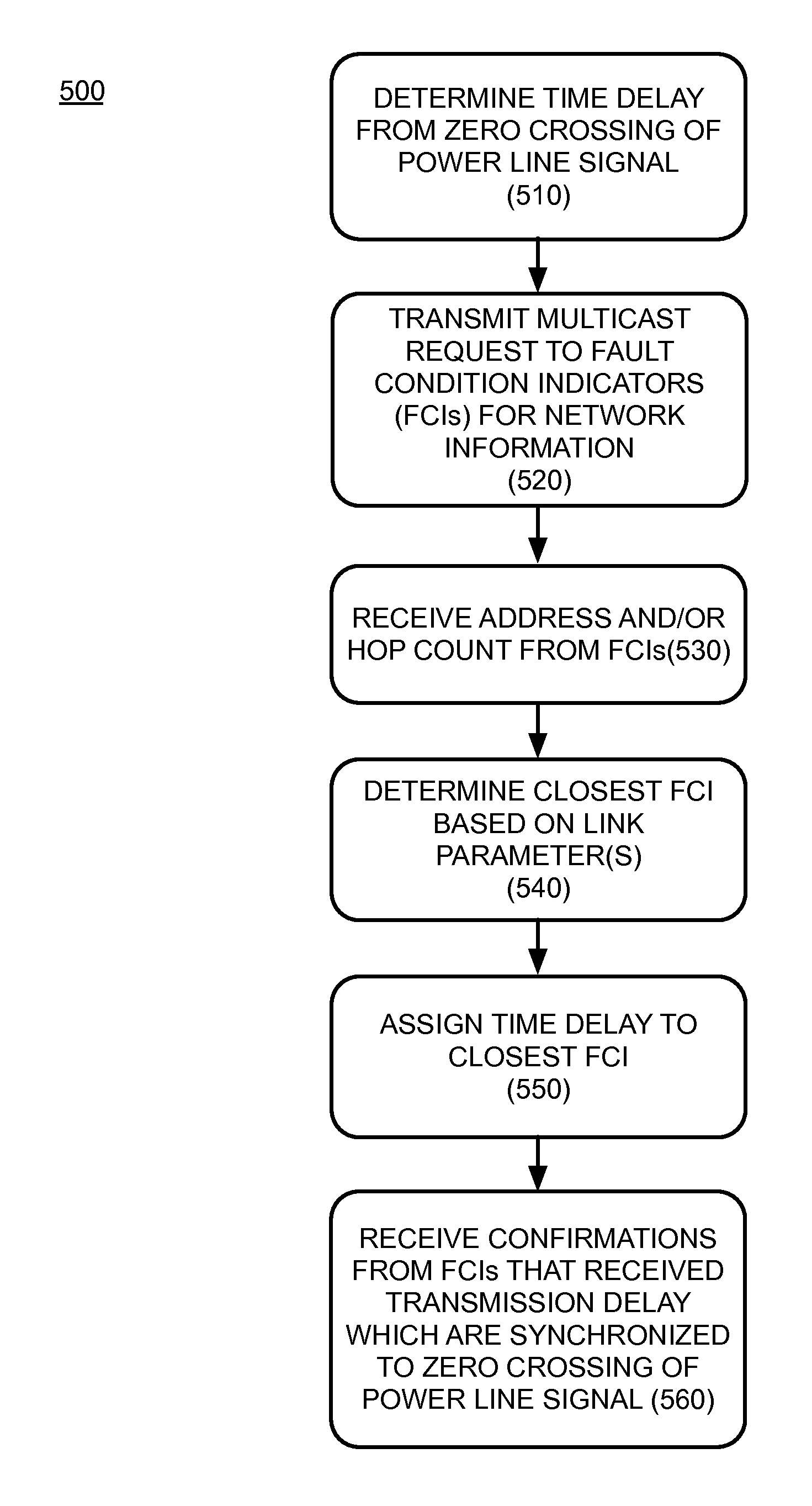
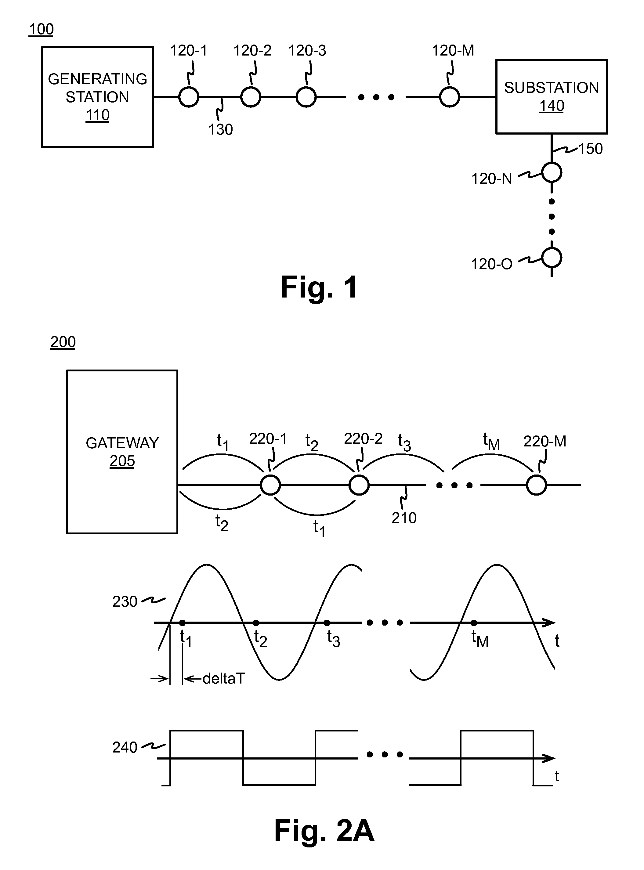
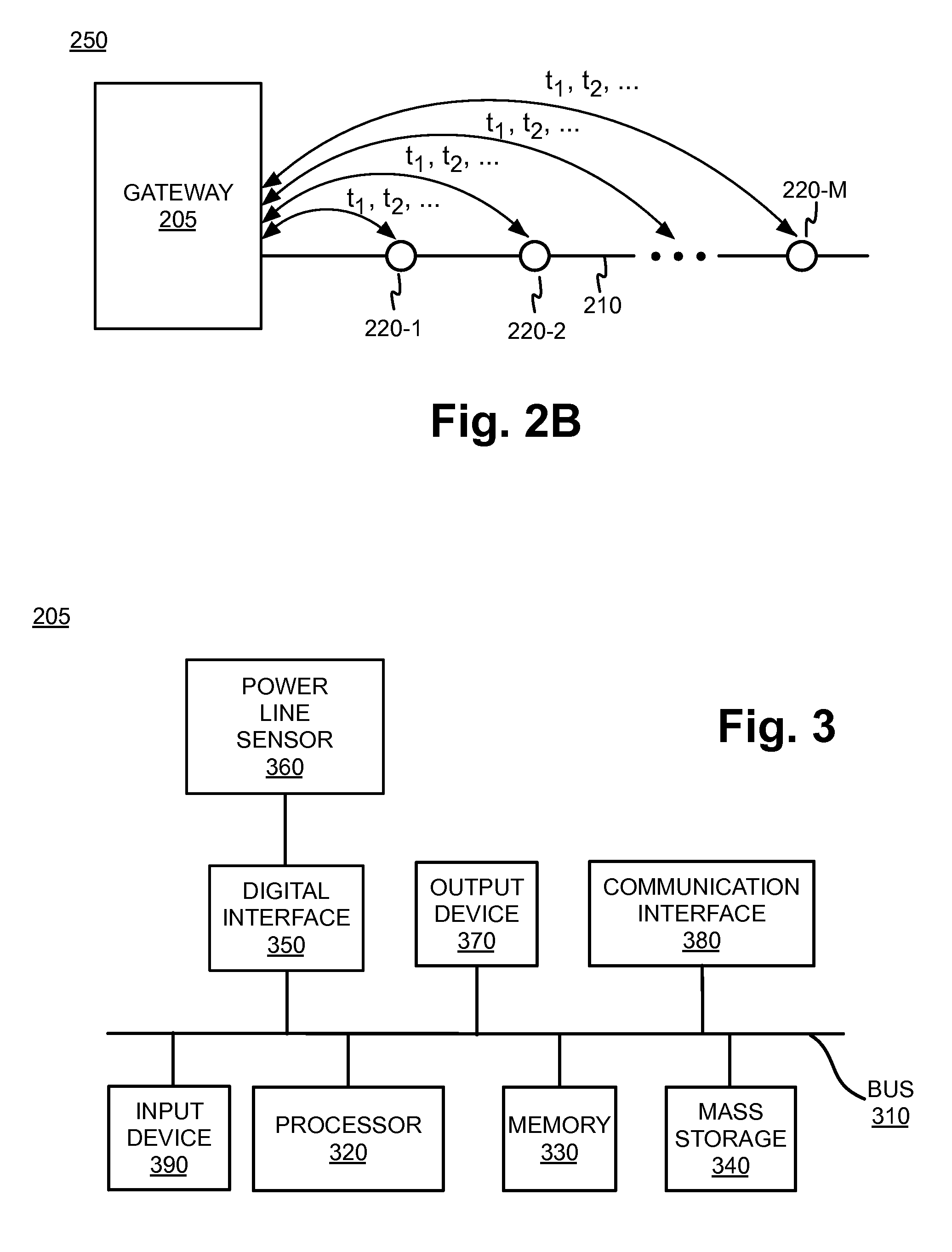
[0013]Embodiments described herein are directed to faulted circuit indicators (FCIs) that may synchronize transmissions based upon the alternative current (AC) oscillation frequency of the power line signal being monitored. Specifically, each of the FCIs may be configured to simultaneously transmit at a time that corresponds to a predefined time delay from a zero crossing of the power line signal, e.g., the time at which the voltage of the AC signal crosses from positive to negative or vice-versa. The predefined time delay may be determined so as to reduce interference of the FCI transmissions that are caused by the power line signal, to eliminate potential collisions with other FCI transmissions, as well as to optimize the power consumption by setting the timing of the message transmissions. The synchronization of t...


PUM


Abstract

A gateway may be configured to synchronize transmissions of a plurality of faulted circuit indicators (FCIs). The gateway may determine a time delay from a zero crossing of a power line signal and obtain network information from the at least one FCI from the plurality of FCIs. The gateway may identify a proximate FCI that is closest to a gateway based on at least one link parameter, and assign the determined time delay to the proximate FCI. The gateway may receive confirmations that at least one FCI received the determined time delay, and has synchronized transmissions based on the determined time delay and the zero crossings of the power signal.

Description

CROSS-REFERENCE TO RELATED APPLICATION[0001]This application claims priority under 35 U.S.C. §119 based on U.S. Provisional Patent Application No. 61 / 978,590 filed Apr. 11, 2014, the disclosure of which is hereby incorporated by reference herein.BACKGROUND OF THE INVENTION[0002]Faulted circuit indicators (FCIs) may be attached to power lines and used to detect electrical faults in power distribution systems. The FCI may detect anomalies in the current and / or voltage of the power line signal, and provide an indication of fault to technicians working to isolate the location of a malfunction in the power distribution system. The indication of a detected fault may be provided, for example, in a visual manner using a mechanical indicator (e.g., a “flag”) and / or a blinking Light Emitting Diode (LED). However, a technician may require a clear line of sight and a close proximity to the FCI in order to reliably observe the visual fault detection indicators “in the field.”[0003]After the prob...

Claims


Application Information

Patent Timeline
Patent Type & Authority Patents(United States)
IPC IPC(8): H04L7/00G08B21/18G01R31/08H02J13/00H04B3/54
CPCG08B21/185H04B3/54H04L7/0041G01R31/08H02J13/0051Y02B90/263Y04S40/123Y04S40/146Y02E60/7892G01R31/086H04L12/10H02J13/00017H02J13/0001H02J13/00034Y04S10/52H02J13/00009Y02B90/20Y02E60/00Y04S40/121
Inventor KHOSHNOOD, BAHMANDODDS, WILLIAM J.DELGADO, CAMILOBRIGHT, EUGENEOCASIO, DAVID
Owner THOMAS & BETTS INT INC
Why Eureka
Try Eureka