Sheet manufacturing apparatus and defibration unit

a technology of defibration unit and manufacturing apparatus, which is applied in the field of sheet manufacturing apparatus and defibration unit, can solve the problems of difficult to meet the demands, difficult to reduce the size of sheet manufacturing apparatus, energy conservation, environmental protection

Active Publication Date: 2016-08-23
SEIKO EPSON CORP
View PDF26 Cites 8 Cited by
  • Summary
  • Abstract
  • Description
  • Claims
  • Application Information

AI Technical Summary

Benefits of technology

[0010]One of the objectives according to several aspects of the present invention is to provide a sheet manufacturing apparatus having a defibration unit for defibrating a defibration object, in which defibration unit it is possible to defibrate without excessively reducing the fiber length and to manufacture a sheet having a strength that is suitable for practical use, as well as to provide such a defibration unit.

Problems solved by technology

The added need for water, power, and large-scale utilities such as drainage equipment also makes it difficult to reduce the size of a sheet manufacturing apparatus.
Therefore, it has been increasingly difficult to meet the demands of recent years for energy conservation, environmental protection, and the like.
A method where absolutely or substantially no water is used, called a dry method, has been anticipated as a method of manufacturing a sheet in place of such a conventional method of papermaking, but the current state of manufacturing sheets has not yet seen any technique that is necessary adequately established for dry manufacturing with consistency to the point of changing from the stock material to a sheet, which is the final product.
However, when the features described in Japanese laid-open patent publication No. 2008-031578 are used and a rotating body is rotated in a state where blades are made to cut into a defibration object composed of the entanglement of fibers or a defibration object obtained when fibers are bound together, then the original fibers end up being shredded by the blades, and many of the resulting fibers are of a shorter fiber length than the original fiber length.
When a sheet is manufactured by such fibers of short fiber length, then there is a concern that there would be fewer fixing points where one fiber fixes to another fiber, and that the strength of the resulting sheet is not adequate.

Method used


Image

  • Sheet manufacturing apparatus and defibration unit
  • Sheet manufacturing apparatus and defibration unit
  • Sheet manufacturing apparatus and defibration unit

Examples


Embodiment Construction

[0039]Several embodiments of the present invention shall be described below. The embodiments described below are illustrative examples of the present invention. The present invention is in no way limited by the following embodiments, and comprises a variety of modified forms that are implemented within a scope where the essence of the present invention is not modified. The configurations described below are not necessarily all essential configurations of the present invention.

1. Sheet Manufacturing Apparatus

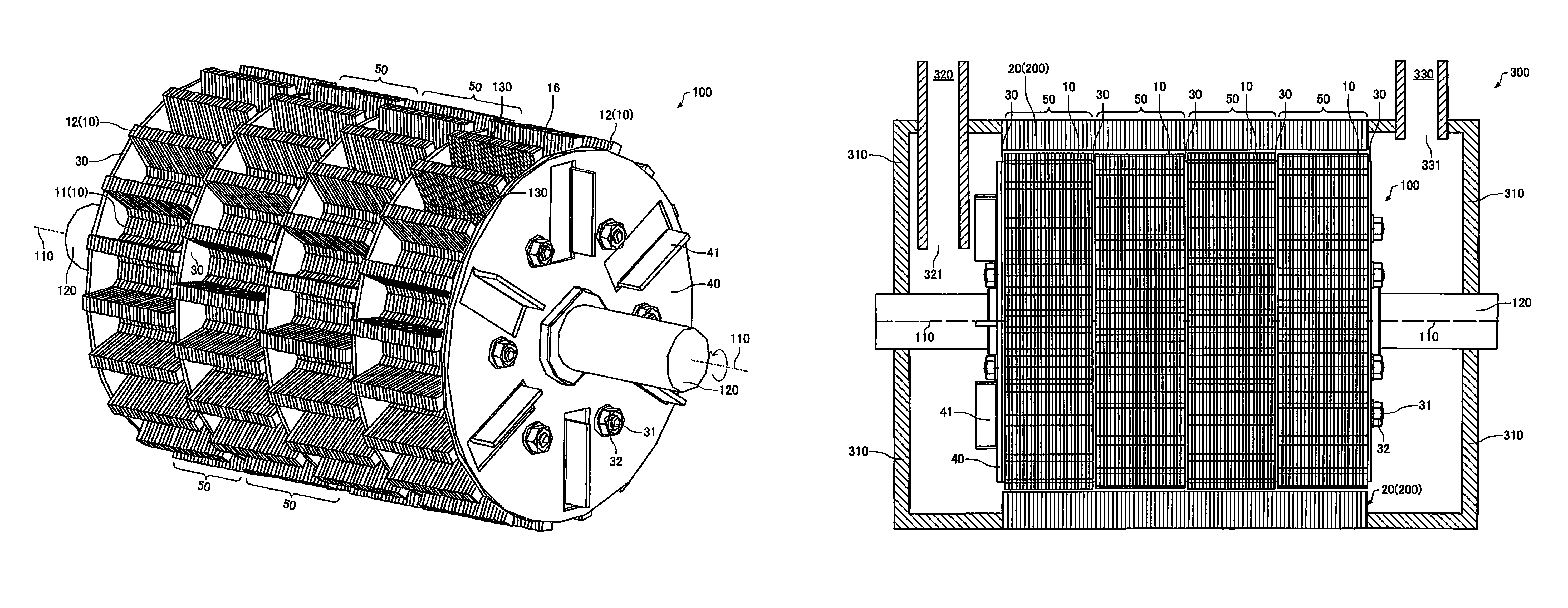
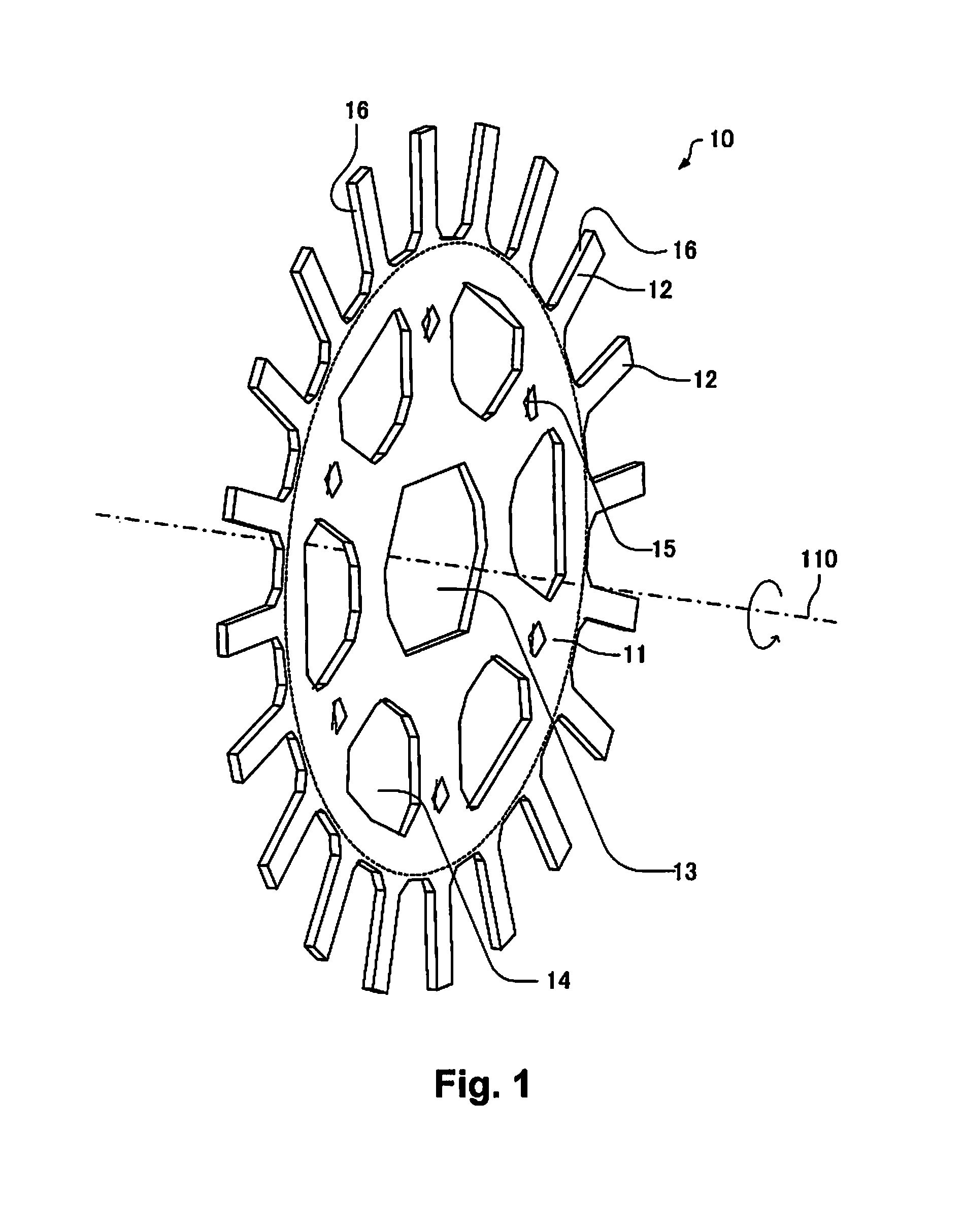
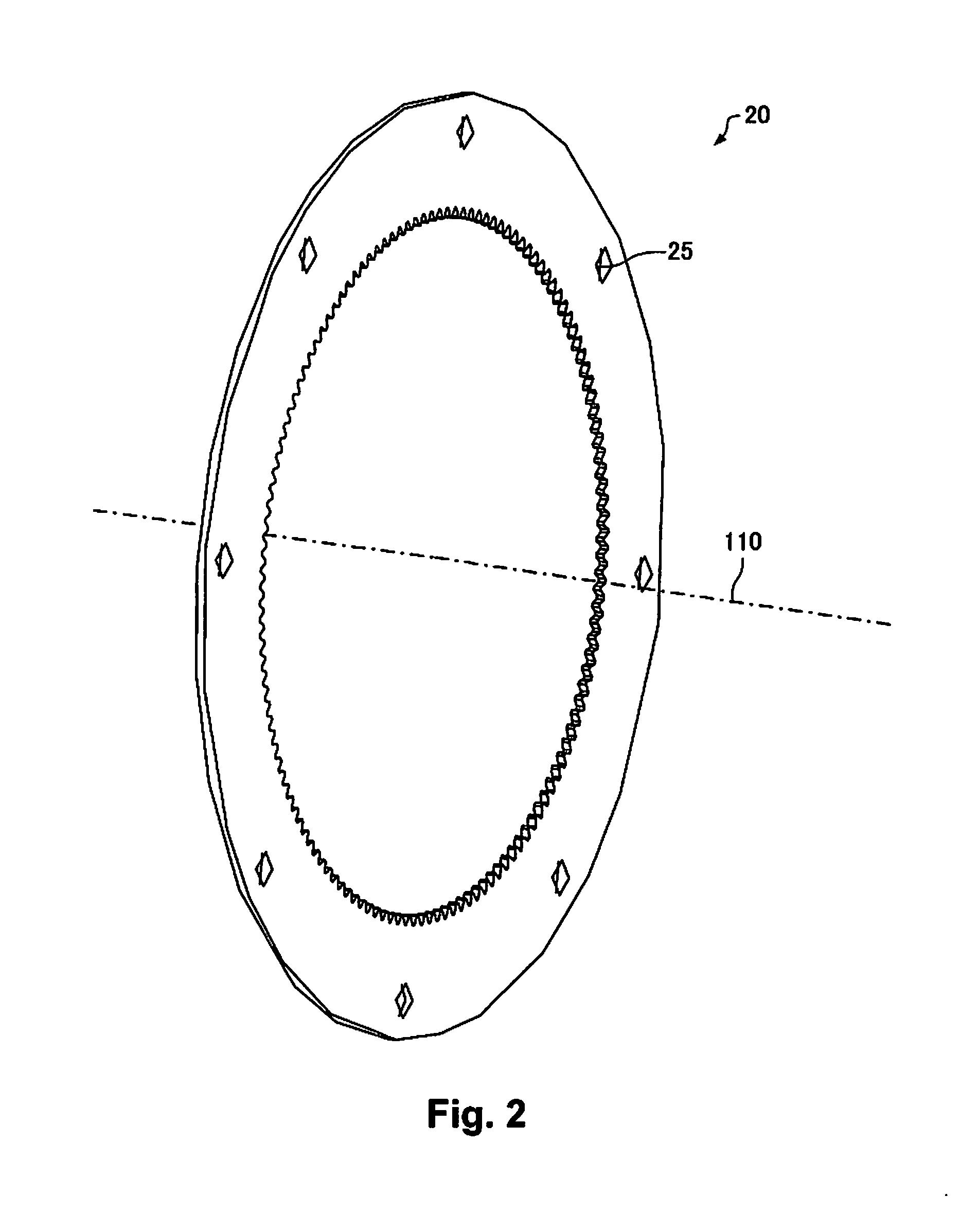
[0040]A sheet manufacturing apparatus 1000 shall be described below, with reference as appropriate to FIGS. 1-8.

[0041]FIG. 1 is a schematic view illustrating a rotating plate 10 of a rotating unit 100. FIG. 2 is a schematic view illustrating a fixing plate 20 of a fixing unit 200. FIG. 3 is a schematic view where the rotating plate 10 and the fixing plate 20 are seen in plan view, and illustrates a state where the rotating plate 10 is arranged on the inside of the fixing plate 20...


PUM

PropertyMeasurementUnit
thicknessaaaaaaaaaa
angleaaaaaaaaaa
thicknessaaaaaaaaaa

Abstract

The sheet manufacturing apparatus in the present invention includes a defibration unit configured to cause a rotating unit to rotate and dry-defibrating a defibration object, and at least a part of defibrated material that has been dry-defibrated is deposited and heated to manufacture a sheet. A plurality of rotating plates provided with a base section located on a central rotation axis side and a plurality of protruding sections that protrude out in a direction drawing away from the central rotation axis are stacked in the rotating unit such that the protruding sections are in contact in a direction in which the central rotation axis extends.

Description

CROSS-REFERENCE TO RELATED APPLICATIONS[0001]This application claims priority to Japanese Patent Application No. 2013-211677 filed on Oct. 9, 2013. The entire disclosure of Japanese Patent Application No. 2013-211677 is hereby incorporated herein by reference.BACKGROUND[0002]1. Technical Field[0003]The present invention relates to a sheet manufacturing apparatus and a defibration unit.[0004]2. Related Art[0005]In the field of sheet manufacturing, a process for conversion into a sheet is generally preceded by a process for converting a material serving as a stock material into fibers (a defibration process). At present, a wet method using a large amount of water is what is mainly used in such a defibration step. As such, steps for water removal, drying, and the like become needed after the sheet has been formed. The added need for water, power, and large-scale utilities such as drainage equipment also makes it difficult to reduce the size of a sheet manufacturing apparatus. Therefore...

Claims


Application Information

Patent Timeline
Patent Type & Authority Patents(United States)
IPC IPC(8): D21D5/24B02C4/00D21B1/06
CPCD21D5/24B02C4/00D21B1/06B02C18/141B02C18/146B29B15/00B29L2007/002
Inventor HIGUCHI, NAOTAKAYAMAGAMI, TOSHIAKIABE, NOBUMASA
Owner SEIKO EPSON CORP
Why Eureka
Try Eureka