
Metrology device and a method for compensating for bearing runout error

a technology of a metalrology device and a bearing runout, which is applied in the direction of mechanical measuring arrangements, liquid/fluent solid measurement, instruments, etc., can solve the problems of difficult tracking of bearing rotation, asynchronous error is more difficult, and the coordinate error of the measurement point is difficult to measur

Active Publication Date: 2016-08-23
FARO TECH INC
View PDF59 Cites 26 Cited by
  • Summary
  • Abstract
  • Description
  • Claims
  • Application Information

AI Technical Summary

Benefits of technology

The technical effects of this patent text include providing a method for accurately determining the position of a metrology device by measuring its angular rotation and generating a transfer function based on the measured rotation. The method involves using an encoder coupled to the bearing and providing an Arduino processor circuit to define a series of sine waves and store them in a memory. The position of the metrology device can then be determined by rotating the bearing and analyzing the signals generated by the encoder. This method can be used in both the field of manufacturing and the construction industry for accurate positioning of metrology devices.

Problems solved by technology

One source of error in the measurement of the coordinates of the measured points is due to bearing runout error at each rotary joint.
It should be appreciated that while the synchronous error may be compensated in the calculation of the coordinates, asynchronous error is more difficult as the coordinate measurement device needs to track the number of rotations of the bearing assembly.
The tracking of the bearing rotation is difficult since the rotary joint may be moved when the coordinate measurement device is in an unpowered state.

Method used


Image

  • Metrology device and a method for compensating for bearing runout error
  • Metrology device and a method for compensating for bearing runout error
  • Metrology device and a method for compensating for bearing runout error

Examples


Embodiment Construction

[0025]Embodiments of the present invention provide advantages in allowing the compensation of synchronous and asynchronous bearing run out error. Embodiments provide further advantages in determining the angular position of the rotary joint when the joint has been rotated with the metrology device in an unpowered state.

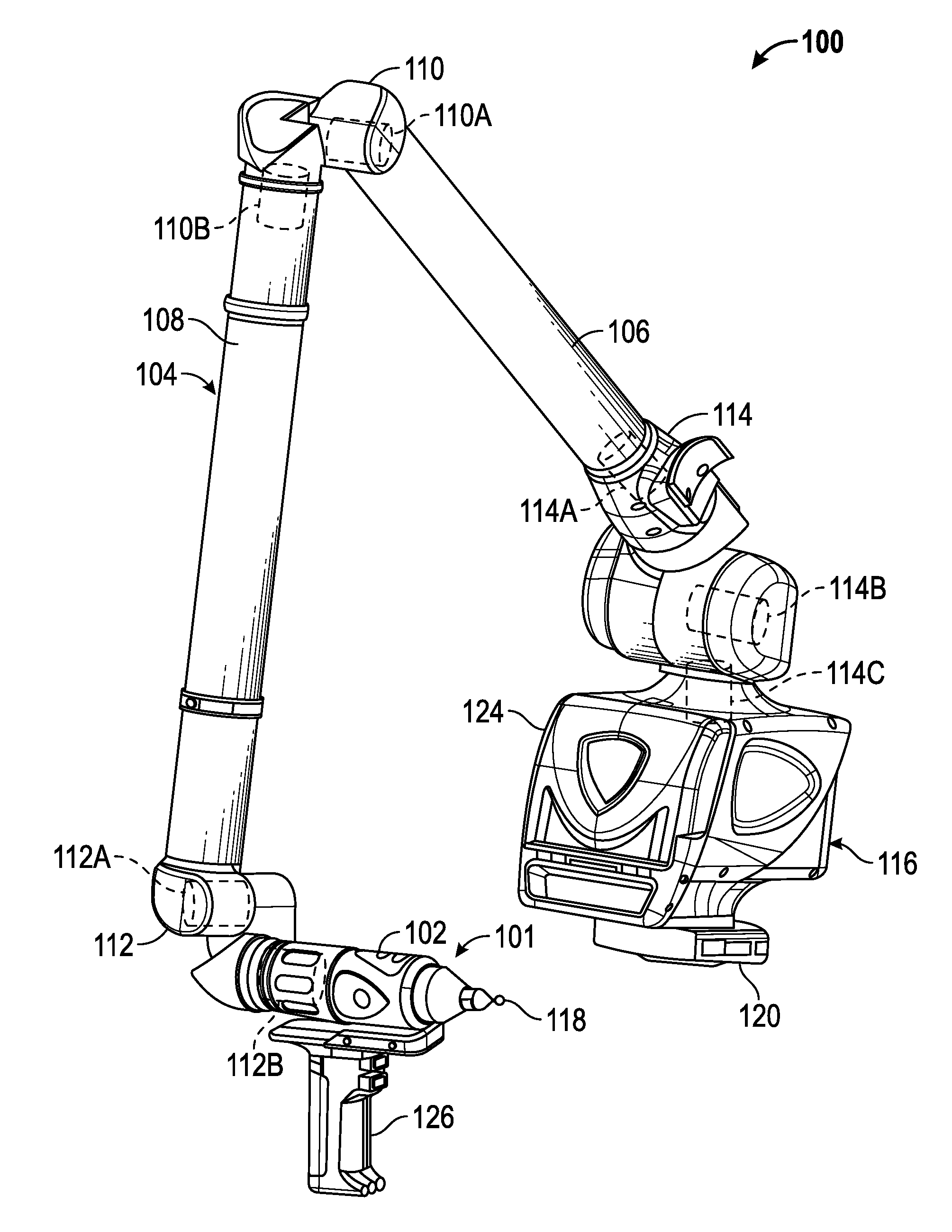
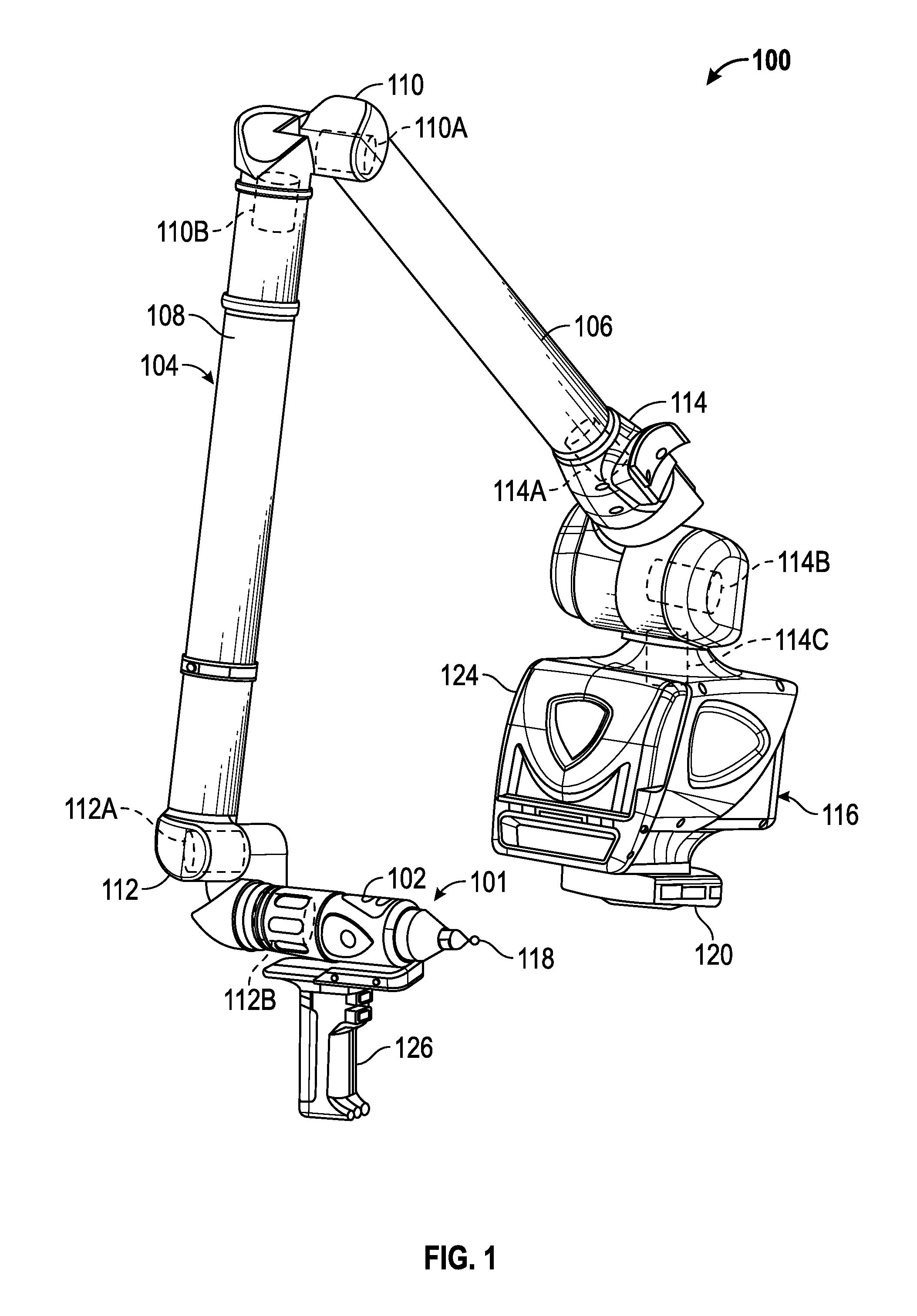
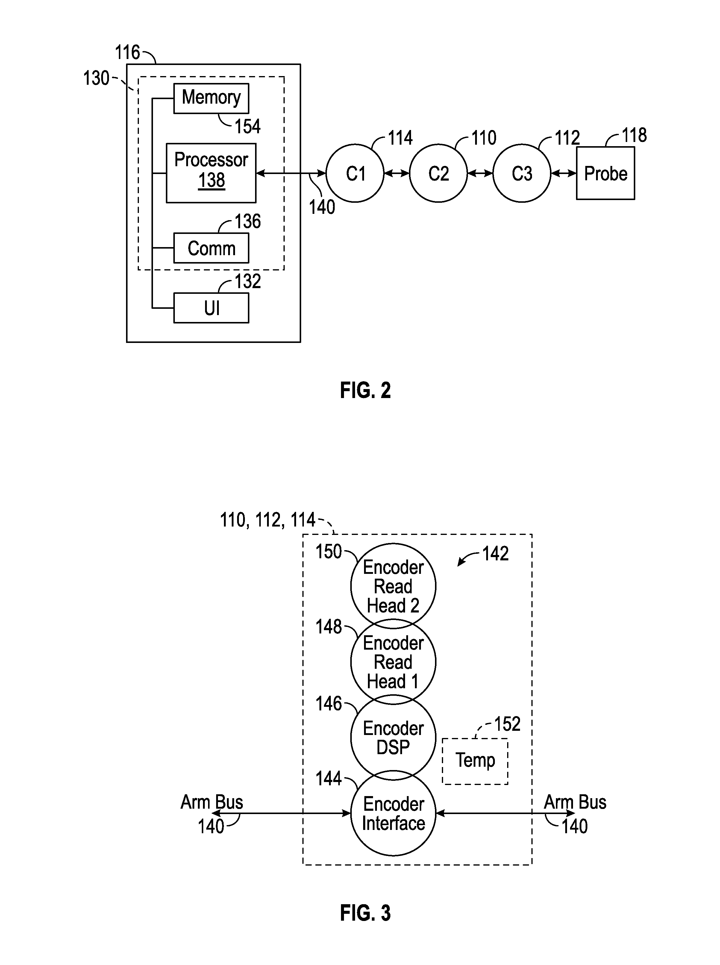
[0026]Referring now to FIG. 1, an AACMM 100 is illustrated according to various embodiments of the present invention, an articulated arm being one type of coordinate measuring device. The exemplary AACMM 100 may comprise a six or seven axis articulated measurement device having a probe end 101 that includes a measurement probe housing 102 coupled to an arm portion 104 of the AACMM 100 at one end. The arm portion 104 comprises a first arm segment 106 coupled to a second arm segment 108 by a first grouping of bearing cartridges 110 (e.g., two bearing cartridges 110A, 110B). A second grouping of bearing cartridges 112 (e.g., two bearing cartridges 112A, 112B) couples the...


PUM


Abstract

A system and method for determining the angular position of a bearing assembly and compensating measurements for bearing runout error in metrology devices, such as an articulated arm coordinate measurement device and a laser tracker, is provided. The system and method includes measuring the bearing runout error and defining a waveform from encoder readings for a first set of rotations. In one embodiment, a transfer function is created based on an analysis of the bearing runout error, such as with a Fourier analysis for example. In another embodiment the bearing runout error is mapped to an absolute angular position. During operation, the angular position of the bearing assembly is determined by comparing a waveform to the waveform from the first set of rotations. With the angular position determined, the bearing runout error may be used to compensate the measurements of the metrology device.

Description

CROSS-REFERENCE TO RELATED APPLICATIONS[0001]The present Application is a Nonprovisional Application that claims the benefit of U.S. Provisional Application Ser. No. 62 / 011,288 filed on Jun. 12, 2014 entitled Metrology Device and a Method for Compensating for Bearing Runout Error, the contents of which are incorporated by reference herein in its entirety.BACKGROUND OF THE INVENTION[0002]The subject matter disclosed herein relates to a metrology device, such as a portable articulated arm coordinate measurement machine (AACMM) or laser tracker, and to a metrology device that can compensate for synchronous and asynchronous bearing runout error.[0003]A metrology device is a device that may be used by an operator to measure and electronically capture coordinates of points on a surface. There are several different types of metrology devices, such as but not limited to: an AACMM, a laser line probe, a laser tracker and an optical structured light scanner for example. The coordinates of the...

Claims


Application Information

Patent Timeline
Patent Type & Authority Patents(United States)
IPC IPC(8): G01B5/00G01D5/244F16C41/00G01D18/00G01D5/347
CPCG01D18/008F16C41/007G01D5/24452G01D5/3473F16C2370/00G01D18/001
Inventor MOY, ERIC J.
Owner FARO TECH INC
Learn More