Hyperstatic truss comprising connecting rods

a connecting rod and hyperstatic technology, applied in the direction of machines/engines, mechanical equipment, transportation and packaging, etc., can solve the problems of generating affecting the production efficiency of the machine, and the loss of the fan blade is likely to generate high compressive and tensile load, so as to achieve the effect of easy adjustment and easy production

Active Publication Date: 2016-08-30
SN DETUDE & DE CONSTR DE MOTEURS DAVIATION S N E C M A
View PDF15 Cites 0 Cited by
  • Summary
  • Abstract
  • Description
  • Claims
  • Application Information

AI Technical Summary

Benefits of technology

[0020]Because the truss is hyperstatic, the loads passing through the connecting rods are determined by the relative strengths of the various connecting rods. The invention has therefore consisted in using connecting rods the compressive strength of which is lower than the tensile strength so that the maximum compressive loads are reduced whereas the maximum tensile loads are increased. The margins with respect to breakage under tension, on the one hand, and with respect to buckling under compression on the other hand, can thus be set independently of one another, allowing for optimal sizing.
[0023]This arrangement makes it possible to choose the best cross section for the internal rod, optimizing the mass of the components, independently of any aerodynamic consideration, and to choose the best profile for the shroud to minimize its drag, independently of any other constraint regarding shape.
[0027]The resistance of the internal rod to buckling is further improved with connecting rods having means of bearing radially against the internal surface of the shroud, so as to prevent the internal rod from buckling when subjected to compressive stress.
[0029]According to another alternative form, the internal rod is threaded, with a plate that is axially movable and forms the bearing surfaces; the connecting rod is thus easier to adjust because the clearance between the bearing surfaces is adjusted by turning the rod. Further, a preload can be applied, so as to have play-free bearing surfaces.
[0030]The solution of the invention has the notable benefit of making it easier to produce a connecting rods shroud that has an aerodynamic profile, because this shroud works only in tension, which means that the shape of the profile need not be taken into consideration for sizing purposes.

Problems solved by technology

The loss of a fan blade is likely to generate high both compressive and tensile loads.
In order to meet this requirement, the main cross section of the connecting rod may be increased, which carries an aerodynamic penalty, or alternatively, the cross-sectional area of the connecting rod may be increased, but this carries a mass penalty.

Method used


Image

  • Hyperstatic truss comprising connecting rods
  • Hyperstatic truss comprising connecting rods
  • Hyperstatic truss comprising connecting rods

Examples


Embodiment Construction

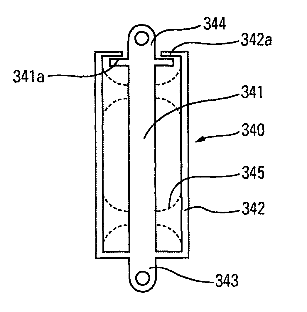
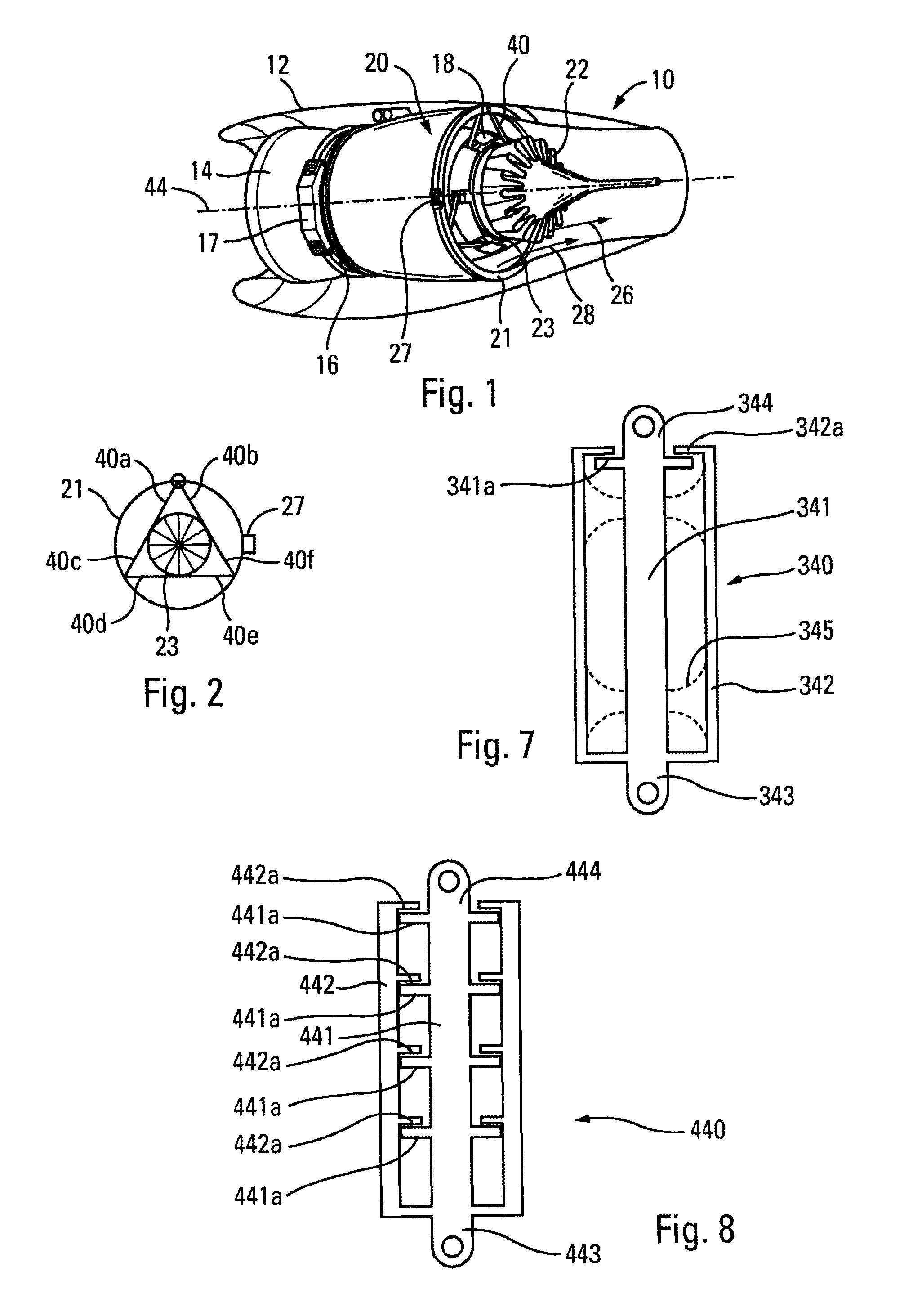
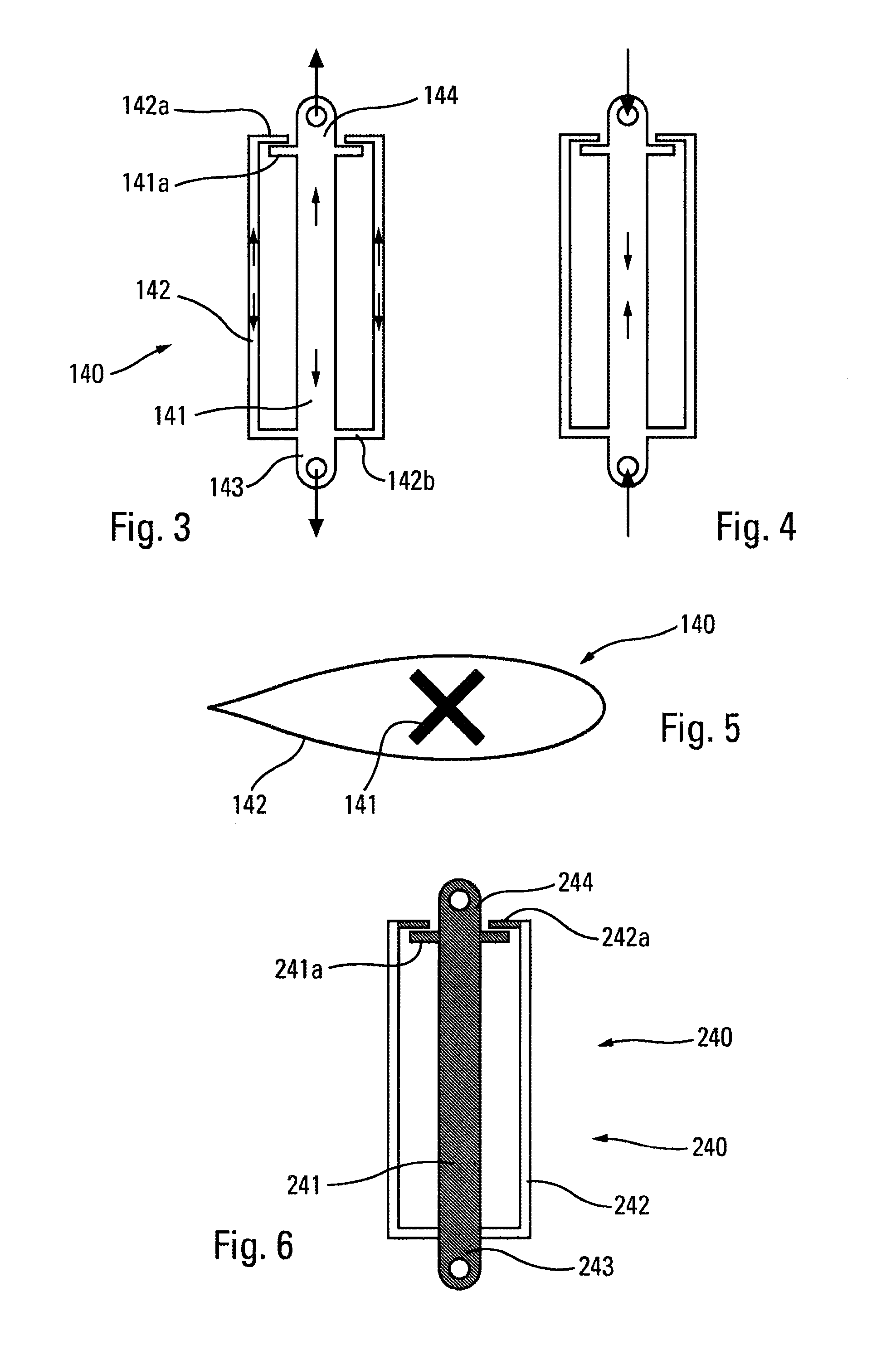
[0042]The turbojet engine 10 of FIG. 1 is a front fan bypass turbojet engine inside a nacelle 12 and comprising, from upstream to downstream, a fan casing 14, an intermediate casing 16 and an annular fan duct formed between two substantially cylindrical cases: an internal case 18 forming the shroud of the part of the engine through which the primary flow passes and forming the gas generator, and an outer case 20. The outer fan duct 20 here extends as far as downstream of the region of confluence between the primary flow 26 and the secondary or bypass flow 28 where the two flows are mixed by the mixer 22. The outer fan duct 20 has a structural function by reacting load between the engine and the aircraft on which it is mounted. It thus comprises a structural ring 21 here connected by connecting rods 40 to the outer ring 23 of the exhaust casing of the gas generator. The engine is secured to the aircraft at the upstream end by an attachment 17 secured to the intermediate casing and at...


PUM


Abstract

A hyperstatic truss including connecting rods, used for suspension of a first ring, forming part of an engine case, inside a second ring concentric to the first ring, the connecting rods being secured at one end to the first ring and at the other end to the second ring. The tensile stiffness of the connecting rods is greater than the compressive stiffness thereof. The truss for example can be used for suspension of a ducted-fan turbine engine with an elongate bypass duct.

Description

BACKGROUND OF THE INVENTION[0001]1. Field of the Invention[0002]The present invention relates to the field of bypass turbojet engines notably comprising an elongate bypass flow casing. It relates to any engine of this type, fixed to the fuselage of the aircraft or military engines.[0003]2. Description of the Related Art[0004]A bypass turbojet engine comprises a fan which when mounted at the front of the engine delivers a flow of compressed air which is divided into two concentric annular flows: a primary flow and a secondary or bypass flow surrounding the primary flow. The latter is guided toward the part of the engine that forms the gas generator and which comprises compression stages, a combustion chamber and a section comprising turbines by which the fan is driven. The primary flow containing the combustion gases is then ejected in an exhaust nozzle. The bypass flow is straightened downstream of the fan and is likewise ejected. In engines for civilian applications, it provides mo...

Claims


Application Information

Patent Timeline
Patent Type & Authority Patents(United States)
IPC IPC(8): F02C1/00F02C7/20F01D25/24B64D27/26
CPCF02C7/20F01D25/246Y02T50/671B64D2027/262B64D2027/266Y02T50/60
Inventor BELLABAL, FRANCOIS ROBERTVINCENT, THOMAS ALAIN CHRISTIAN
Owner SN DETUDE & DE CONSTR DE MOTEURS DAVIATION S N E C M A
Why Eureka
Try Eureka