Liquid crystal composition and liquid crystal display device
What is AI technical title?
AI technical title is built by Patsnap AI team. It summarizes the technical point description of the patent document.
a liquid crystal composition and display device technology, applied in the field of liquid crystal compositions, can solve the problems of image persistence, large device contrast ratio, small electric power consumption, etc., and achieve the effects of small viscosity, large specific resistance, and high stability to ultraviolet ligh
Inactive Publication Date: 2016-09-06
JNC CORP +1
View PDF6 Cites 8 Cited by
Summary
Abstract
Description
Claims
Application Information
AI Technical Summary
This helps you quickly interpret patents by identifying the three key elements:
Image
Click on the blue label to locate the original text in one second.
Reading with bidirectional positioning of images and text.
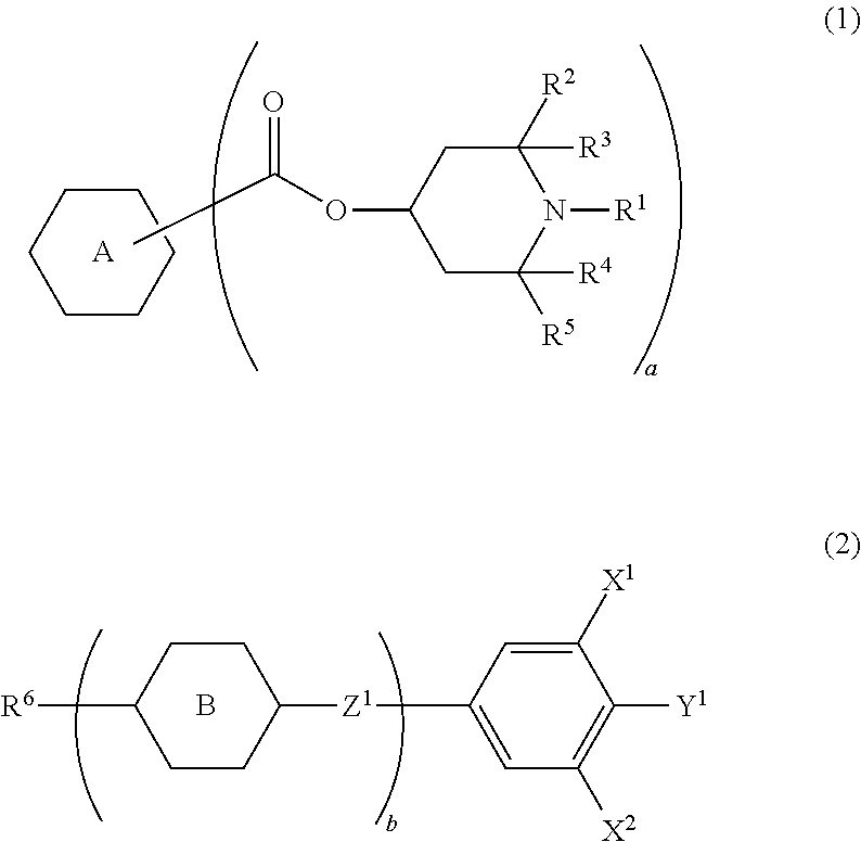
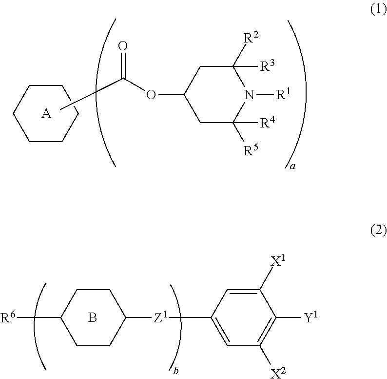
CROSS-REFERENCE TO RELATED APPLICATION[0001]This application claims the priority benefit of Japan application serial no. 2014-153674, filed on Jul. 29, 2014 and Japan application serial no. 2015-009403, filed on Jan. 21, 2015. The entirety of each of the above-mentioned patent applications is hereby incorporated by reference herein and made a part of this specification.TECHNICAL FIELD[0002]The invention relates to a liquid crystal composition, a liquid crystal display device including the composition and so forth. In particular, the invention relates to a liquid crystal composition having a positive dielectric anisotropy and an active matrix (AM) device that includes the composition and has a mode such as a TN mode, an OCB mode, an IPS mode, an FFS mode or an FPA mode.BACKGROUND ART[0003]In a liquid crystal display device, a classification based on an operating mode for liquid crystal molecules includes a phase change (PC) mode, a twisted nematic (TN) mode, a super twisted nematic (...
Claims
Application Information
Patent Timeline
Application Date:The date an application was filed.
Publication Date:The date a patent or application was officially published.
First Publication Date:The earliest publication date of a patent with the same application number.
Issue Date:Publication date of the patent grant document.
PCT Entry Date:The Entry date of PCT National Phase.
Estimated Expiry Date:The statutory expiry date of a patent right according to the Patent Law, and it is the longest term of protection that the patent right can achieve without the termination of the patent right due to other reasons(Term extension factor has been taken into account ).
Invalid Date:Actual expiry date is based on effective date or publication date of legal transaction data of invalid patent.

