Torsional vibration damping device

a technology of vibration damping device and rotary member, which is applied in the direction of vibration suppression adjustment, mechanical equipment, and machining details, etc., can solve the problems of increasing the number of components of the vibration damping device, increasing the number of coatings, and and achieving excellent abrasion resistance and durability. , the effect of easy tuning and maintenan

Inactive Publication Date: 2016-09-06
TOYOTA JIDOSHA KK
View PDF14 Cites 7 Cited by
  • Summary
  • Abstract
  • Description
  • Claims
  • Application Information

AI Technical Summary

Benefits of technology

[0007]The present invention has been conceived noting the foregoing technical problems, and it is therefore an object of the present invention is to provide a torsional vibration damping device excellent in abrasion resistance and durability whose vibration damping characteristics can be tuned and maintained easily.
[0019]According to the present invention, the inertial mass rotated together with the rotary member is oscillated in the circumferential direction by torque pulses exerted to the rotary member. Consequently, torsional vibrations of the rotary member are damped by such oscillating motion of the inertial mass. In this situation, the lubrication oil held in the chamber centrifugally adheres to an inner face of radially outer section of the chamber to form the oil film. A thickness (or a depth) of the oil film is governed by an amount of the lubrication oil encapsulated in the chamber. However, according to the present invention, the amount of the lubrication oil is adjusted in a manner such that the inertial mass is allowed to be oscillated without come into contact with the oil film or brought into contact only at some point in the oscillation path. That is, the inertial mass will not be immersed entirely into the lubrication oil in the course of oscillation. According to the present invention, therefore, resistance of the inertial mass to oscillate caused by the lubrication oil can be reduced so that the inertial mass is allowed to oscillate at the designed frequency. In addition, since inertial mass is not brought into contact with the lubrication oil, the vibration damping characteristics can be maintained precisely.
[0020]When the rotary member stops, the lubrication oil is concentrated at a bottom of the chamber so that the inertial mass can be immersed partially into the lubrication oil to be lubricated. The lubrication oil adhering to the inner face of the radially outer section of the chamber is agitated during increasing or decreasing a rotational speed of the rotary member while forming an oil film on the inertial mass and in the vicinity thereof. That is, the inner face of the chamber and other contact sites with the inertial mass can be lubricated. According to the present invention, therefore, the vibration damping characteristics of the torsional vibration damping device will not be changed frictionally, and the torsional vibration damping device can be prevented from being damaged.
[0021]The oil reservoir arranged on radially outer side of the chamber is adapted to reduce a thickness of the oil film centrifugally formed on the inner face of the chamber. According to present invention, therefore, the thickness of the oil film can be kept thinner even if an amount of the lubrication oil in the chamber is increased so that the inertial mass can be displaced radially outwardly to enhance an inertial torque for damping torsional vibrations.
[0022]In addition to the above-mentioned advantages, the foreign matter contained in the lubrication oil such as metal powder resulting from metal processing and abrasion powder generated during operation can be captured by the foreign matter capturing member such as the magnet and the strainer. According to the present invention, therefore, the inertial mass is allowed to be oscillated smoothly without causing abrasion at the contact site.
[0023]Further, the lubrication oil agitated by a change in a rotational speed of the rotary member can be guided by the guide member toward the inertial mass and the raceway surface so that the contact therebetween can be lubricated effectively.

Problems solved by technology

The pendulum mass is oscillated by the torque pulse of the pulley as long as the pulley is rotated, and hence the pin and a pin hole are always subjected to high friction.
However, an additional work for forming the coating is required during a manufacturing process, and a number of components of the vibration damping device has to be increased.
Therefore, it is rather difficult to keep oscillating the mass at the desired frequency.

Method used


Image

  • Torsional vibration damping device
  • Torsional vibration damping device
  • Torsional vibration damping device

Examples


Embodiment Construction

)

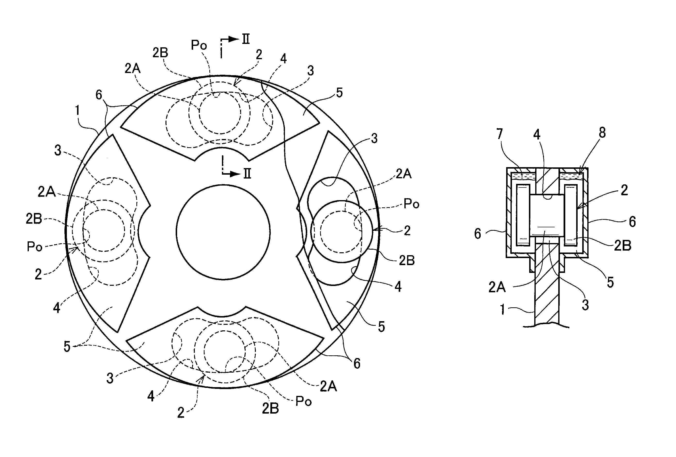
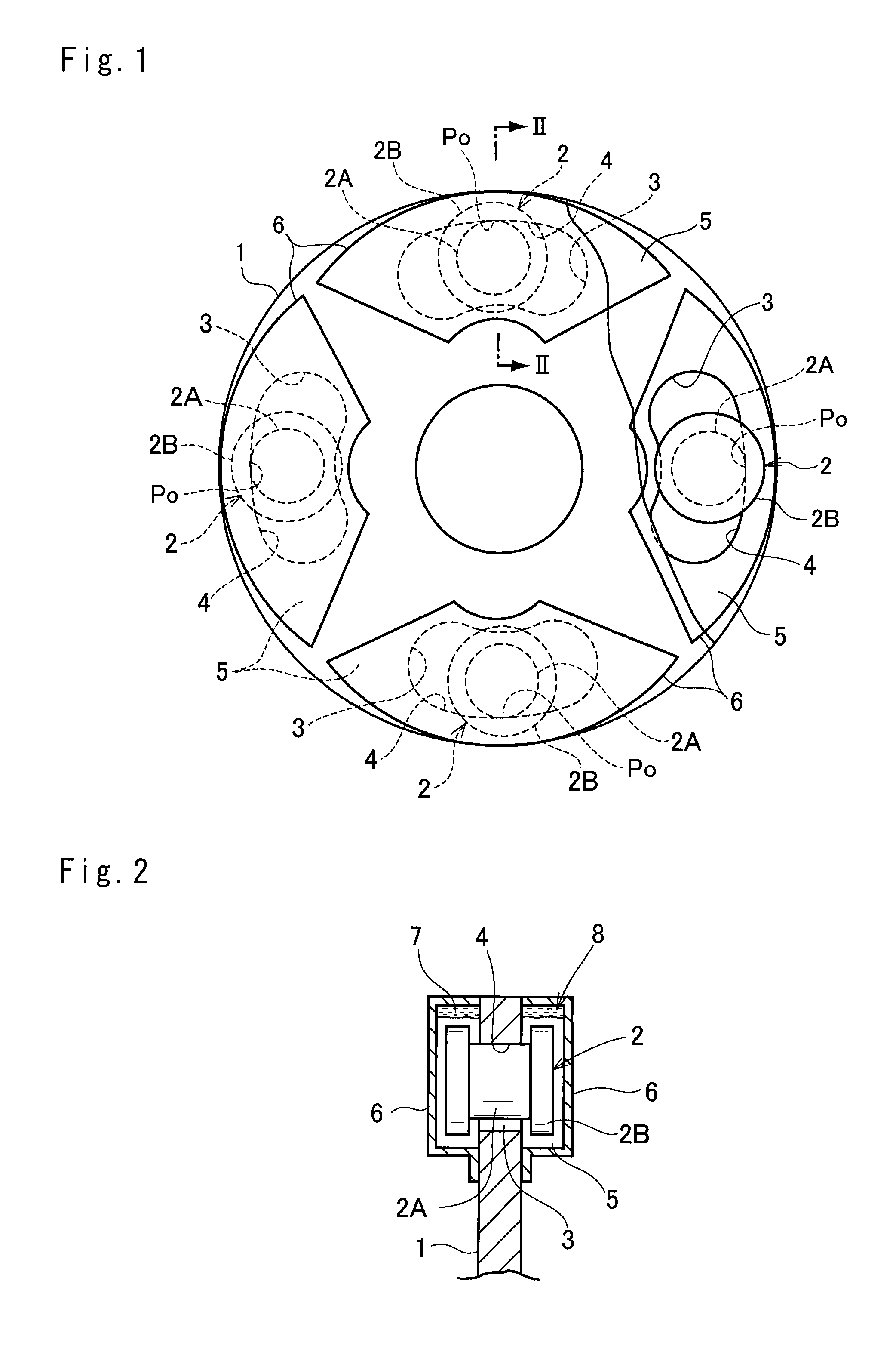
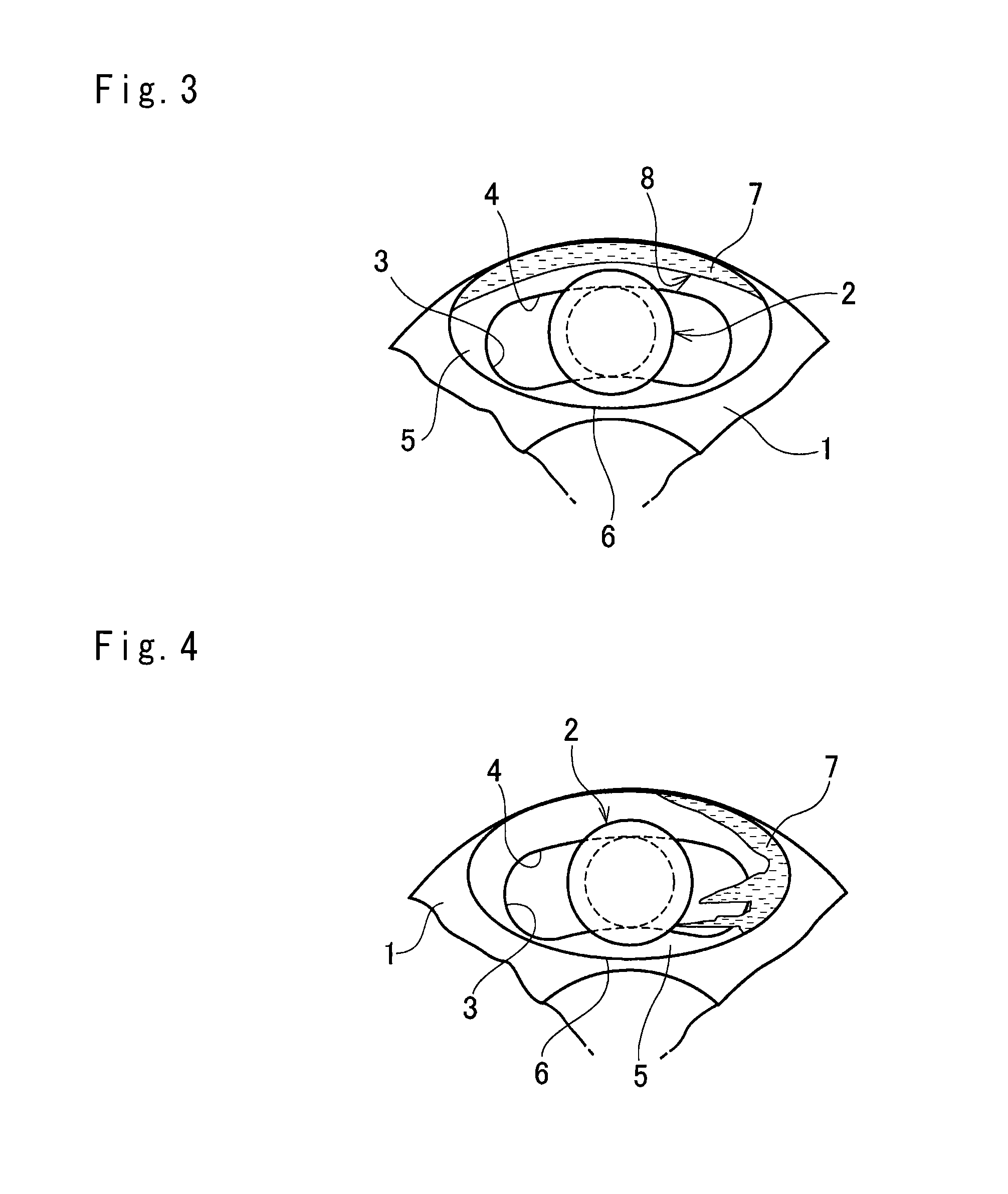
[0043]Next, preferred example of the torsional vibration damping device will be explained in more detail. Specifically, the torsional vibration damping device according to the preferred example is a dynamic damper adapted to damp torsional vibrations of a rotary member resulting from torque pulses by pendulum motion of an inertial mass. In order to counteract to such torque pulses, the inertial mass is allowed to pivot around a shaft or pin, or to oscillate along a raceway surface formed in the rotary member. For example, the former structure in which the inertial mass is pivotally fixed to the rotary member is described in Japanese Patent Laid-Open No. 2002-340097 and the Japanese Patent Laid-Open No. 2011-504987. The latter structure in which the inertial mass rolls on the raceway surface is disclosed in Japanese Patent Laid-Open 2001-153185.

[0044]The preferred examples to be explained relate to the dynamic damper configured to damp vibrations by an oscillating motion of the iner...


PUM


Abstract

The present invention relates to a torsional vibration damping device in which a contact site with an inertial mass can be lubricated effectively while reducing resistance of the inertial mass to oscillate. The vibration damping device includes a rotary member that is rotated by a torque, and an inertial mass that is oscillated by torque pulses. The inertial mass is held in a chamber formed on the rotary member liquid-tightly together with lubrication oil while being allowed to be oscillated by torque pulses in the rotational direction of the rotary member. An amount of the lubrication oil is adjusted in a manner such that the inertial mass will not be brought into contact with an oil film of the lubrication oil centrifugally adhering to a radially outer section of an inner face of the chamber.

Description

TECHNICAL FIELD[0001]The present invention relates to a device for damping torsional vibrations of a rotary member such as a crankshaft and a power transmission shaft, and more particularly, to a device for damping torsional vibrations utilizing oscillating motion of a rolling mass.BACKGROUND ART[0002]For instance, a device for suppressing resonance by an oscillating motion of an inertial mass is described in Japanese Patent Laid-Open No. 2002-340097. In a device taught by Japanese Patent Laid-Open No. 2002-340097, a pendulum mass is pivotally fixed to a radially outer side of a pulley by a pin, and a natural frequency of the pendulum mass governed by a distance between the pin and a gravity center thereof is adjusted to a number of torque pulses per rotation. The pendulum mass is oscillated by the torque pulse of the pulley as long as the pulley is rotated, and hence the pin and a pin hole are always subjected to high friction. In order to ease such friction between the hole and th...

Claims


Application Information

Patent Timeline
Patent Type & Authority Patents(United States)
IPC IPC(8): F16F15/14F16H57/04
CPCF16F15/145F16H57/0402Y10T74/2121
Inventor AIJIMA, SHINGOMIYAHARA, YUTSUKANO, FUSAHIROAMANO, HIROYUKIYOSHINO, HIROTSUGUSEKIGUCHI, TADASHIHORITA, SYUHEIKISHIMOTO, NAOYUKIMIYAMACHI, YOSHIHIRO
Owner TOYOTA JIDOSHA KK
Why Eureka
Try Eureka