Inflatable structure with braided layer

a technology of balloons and braided layers, which is applied in the field of composite structures of medical balloons, can solve problems such as delicate materials, and achieve the effect of consistent, predictable, or tighter balloon folding

Active Publication Date: 2016-09-13
CR BARD INC
View PDF25 Cites 1 Cited by
  • Summary
  • Abstract
  • Description
  • Claims
  • Application Information

AI Technical Summary

Benefits of technology

[0014]A balloon for medical treatments such as percutaneous transluminal coronary angioplasty (PTCA), delivery of a vascular stents or stent grafts, employs reinforcement materials that are patterned so as to promote consistent, predictable, or tighter, folding of the balloon.

Problems solved by technology

Braiding can be done with very delicate materials.

Method used


Image

  • Inflatable structure with braided layer
  • Inflatable structure with braided layer
  • Inflatable structure with braided layer

Examples


Embodiment Construction

[0060]The various embodiments will be described in detail with reference to the accompanying drawings. Wherever possible, the same reference numbers will be used throughout the drawings to refer to the same or like parts.

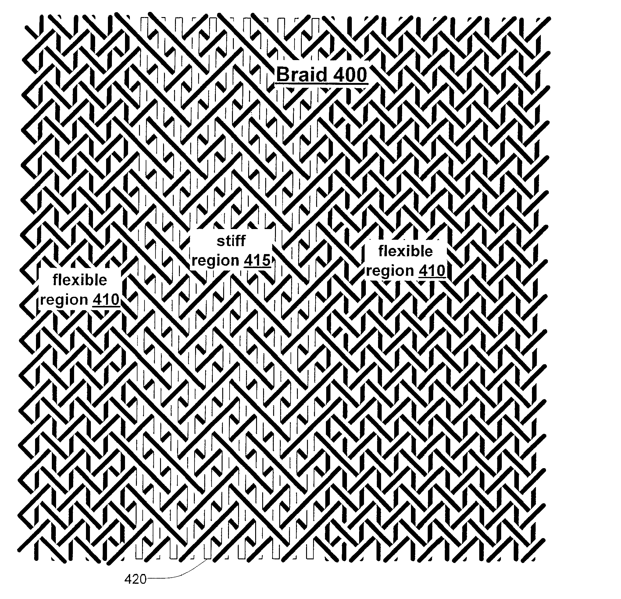
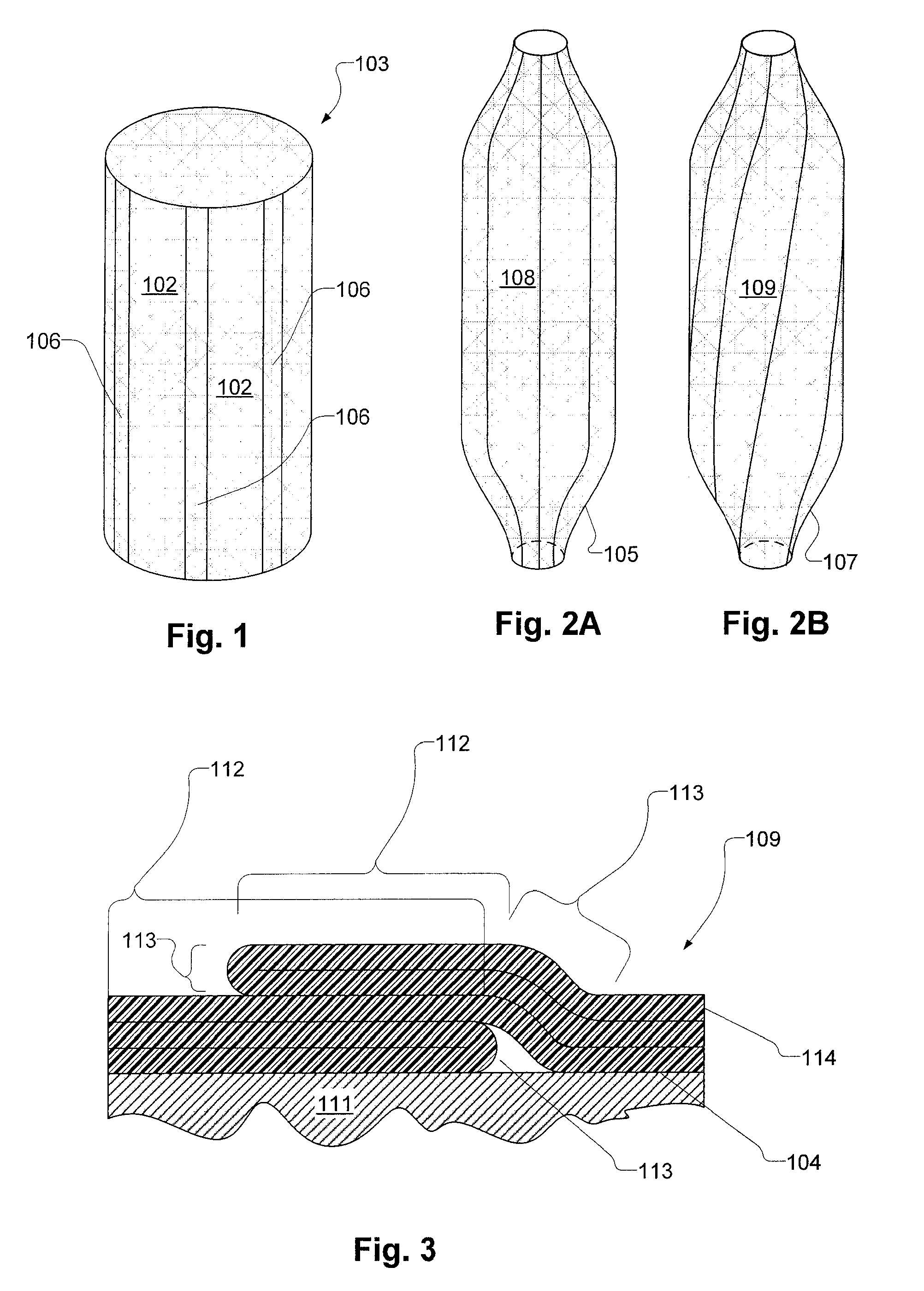
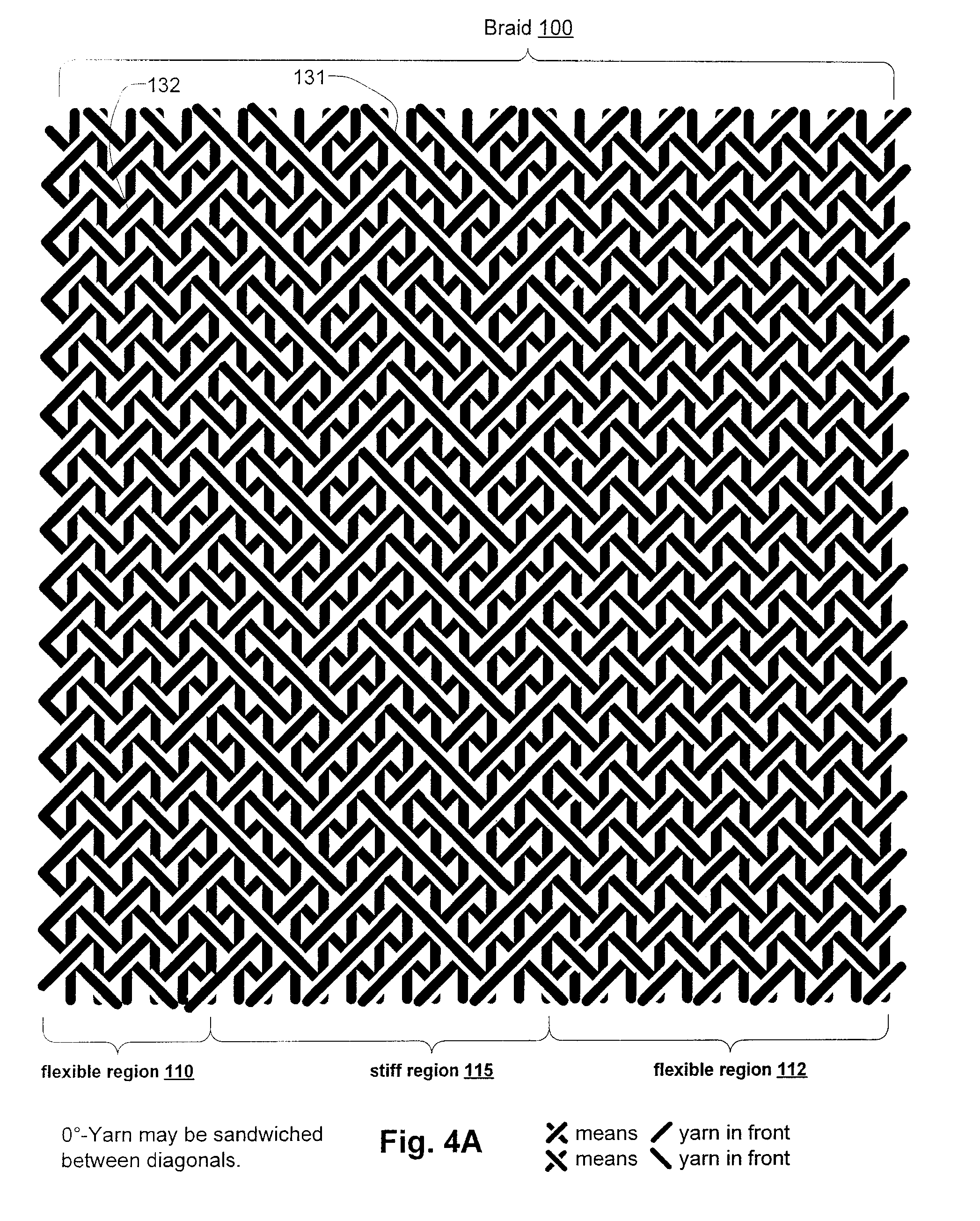
[0061]FIG. 1 shows a reinforcement structure, such as a tube braid, that may be used in a composite balloon, the reinforcement structure having relatively flexible portions 106 or facets and relatively stiff portions 102 or facets. A tubular braid 103 has stiff portions 102 that are relatively stiff, or at least relatively stiff in the circumferential direction (i.e., the direction about the balloon axis). The tubular braid 103 also has flexible portions 106 that are flexible relative to the stiff portions 102, also, at least in the circumferential direction.

[0062]The tube braid 103 may be of strong filaments (not shown separately) of any type, but in the present embodiments of folding medical balloons, they include relatively inelastic high strength synthetic fiber...


PUM


Abstract

A balloon for medical treatments such as percutaneous transluminal coronary angioplasty (PTCA), delivery of a vascular stents or stent grafts, employs reinforcement materials that are patterned so as to promote consistent folding of the balloon. The reinforcements may be fiber fabric reinforcements and the balloon may be used for biocidal treatment.

Description

PRIORITY CLAIM AND INCORPORATION BY REFERENCE[0001]The present application claims priority to U.S. Provisional Application Ser. No. 60 / 829,231, filed Oct. 12, 2006, hereby incorporated by reference in its entirety.TECHNICAL FIELD[0002]The invention relates to composite structures for medical balloons and in particular, such structures that promote predictable folding.BACKGROUND ART[0003]Woven and braided fabrics have been used to reinforce various devices. Compared to weaving, braiding may impart greater strength for a unit of weight. The strength of a braid comes from the fact that multiple yarns can be intertwined without any being twisted around another. Generally these are continuously braided at an angle and there is no need for any yarn to suffer a sharp bend. As a result, loads may be distributed evenly and efficiently throughout the braid.[0004]Automated fabrication of braids generally results in tubular or flat configurations. Braids can also be formed without any underlyin...

Claims


Application Information

Patent Timeline
Patent Type & Authority Patents(United States)
IPC IPC(8): A61M29/00A61M29/02A61F2/958A61M25/10
CPCA61M29/02A61M25/1029A61M25/1038A61F2/958A61F2250/0018A61F2250/0039A61M25/1011A61M2025/1031A61M2025/1084D04C1/02D10B2403/02411D10B2509/06A61M25/1002A61M2025/1004A61M2025/1088A61M25/104A61P31/00A61P31/04A61M25/10A61M2025/1075A61M2025/1079
Inventor SIMPSON, CHARLES L.
Owner CR BARD INC
Why Eureka
Try Eureka