
Bleeding mechanism for use in a propulsion system of a recoilless, insensitive munition

a propulsion system and recoilless technology, applied in missile propulsion, weapons, ammunition storage, etc., can solve the problems of difficult utilization of heat sensitive materials to allow the countermass to drain, the common practice of venting the propulsion system is not feasible, and the hole cut in the barrel would compromise the integrity of the barrel, etc., to achieve good insulation, prevent the effect of heat loss and easy maintenan

Active Publication Date: 2016-09-13
UNITED STATES OF AMERICA THE AS REPRESENTED BY THE SEC OF THE ARMY
View PDF5 Cites 7 Cited by
  • Summary
  • Abstract
  • Description
  • Claims
  • Application Information

AI Technical Summary

Benefits of technology

The patent describes a device that improves the performance of a missile's warhead by using an inertial measurement system (IMF). The warhead is designed to withstand the heat of a cook-off and is protected from damage by a filament wound barrel, which is a good insulator and helps to restrict the flow of heat. By positioning the device outside the weapon, it can quickly react to changes in temperature. Overall, this technology makes the missile more accurate and reliable.

Problems solved by technology

Because cutting holes in these barrels would compromise their integrity, the common practice of venting the propulsion system will not be feasible.b. The utilization of heat sensitive materials to allow the countermass to drain will be difficult because the countermass behaves as a heat sink, preventing the heat sensitive materials from heating durng a cook off.c. Other features located within the barrel relied on heat to activate, but the percussion cap located on the surface of the barrel is exposed to the heat much earlier than the in-barrel features.d.
While eutectic alloys have an excellent temperature response, the processes to solder these components lack an industrial base for full rate production.
Additionally, the eutectic alloy is costly.
The warhead may become armed and detonate, which fails IM with a Type 1 detonation.
The bleeding mechanism would be activated by excess heat, and as a result, it would cause the countermass container to rupture.
The need for such a bleeding mechanism has heretofore remained unsatisfied.

Method used


Image

  • Bleeding mechanism for use in a propulsion system of a recoilless, insensitive munition
  • Bleeding mechanism for use in a propulsion system of a recoilless, insensitive munition
  • Bleeding mechanism for use in a propulsion system of a recoilless, insensitive munition

Examples


Embodiment Construction

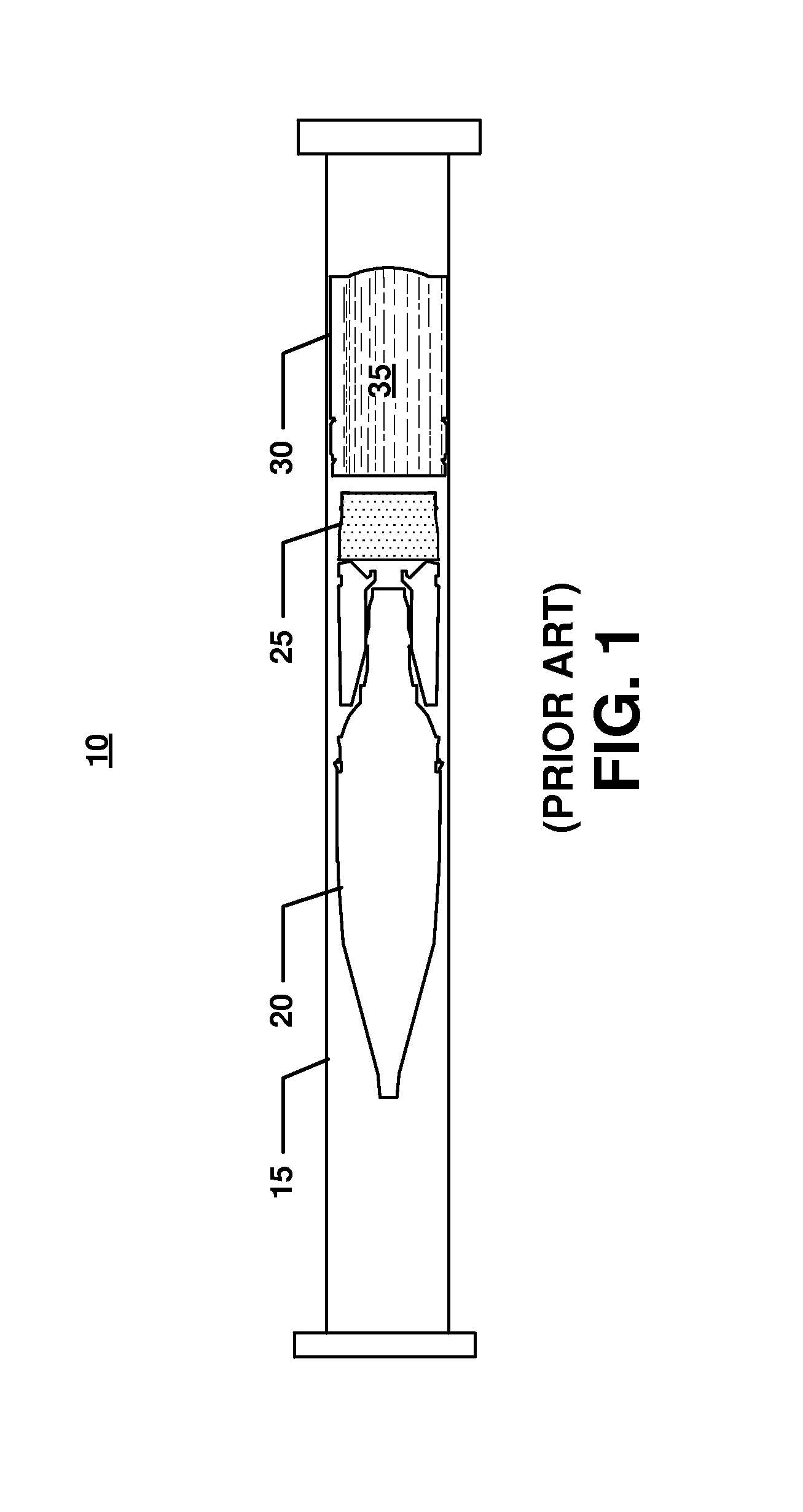
[0056]FIG. 1 is a representation of a conventional recoilless, insensitive munition 10 having a tubular barrel or launch tube 15. A warhead or projectile 20 is placed within the launch tube 15. A propulsion system 25 and a liquid filled countermass container 30 are also housed within the launch tube 15, behind the projectile 20.

[0057]Since the insensitive munition 10 often utilizes a filament wound barrel 15 in order to maximize strength and minimize weight, cutting holes in the barrel 15 to allow the countermass 35, within the countermass container 30, will compromise the integrity of the insensitive munition 10, and is therefore neither feasible nor recommended.

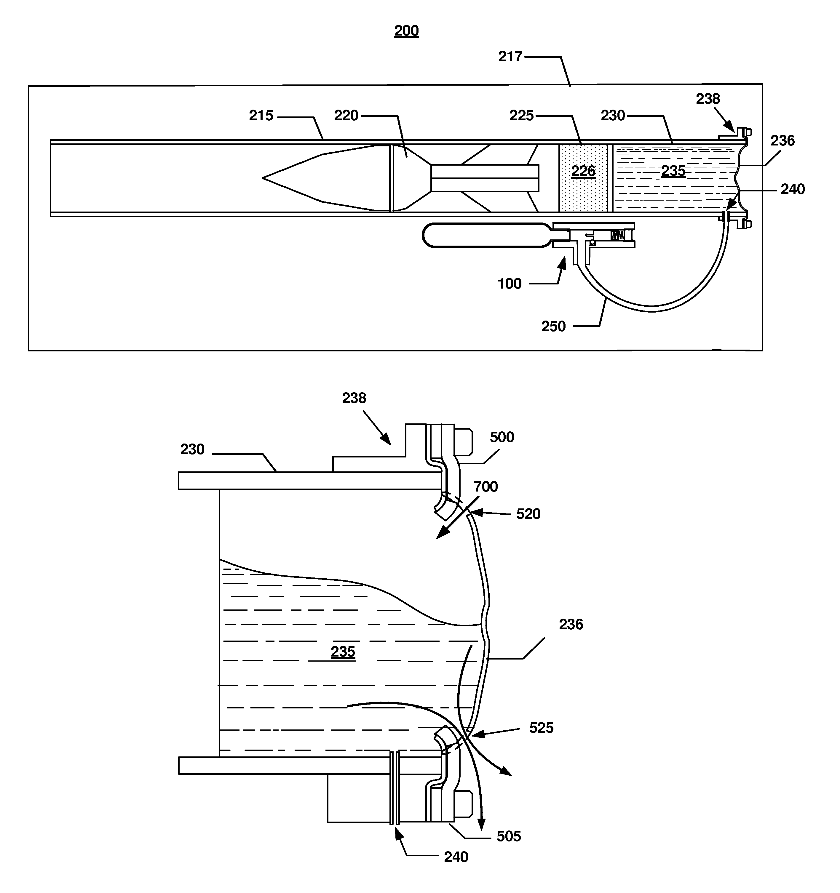
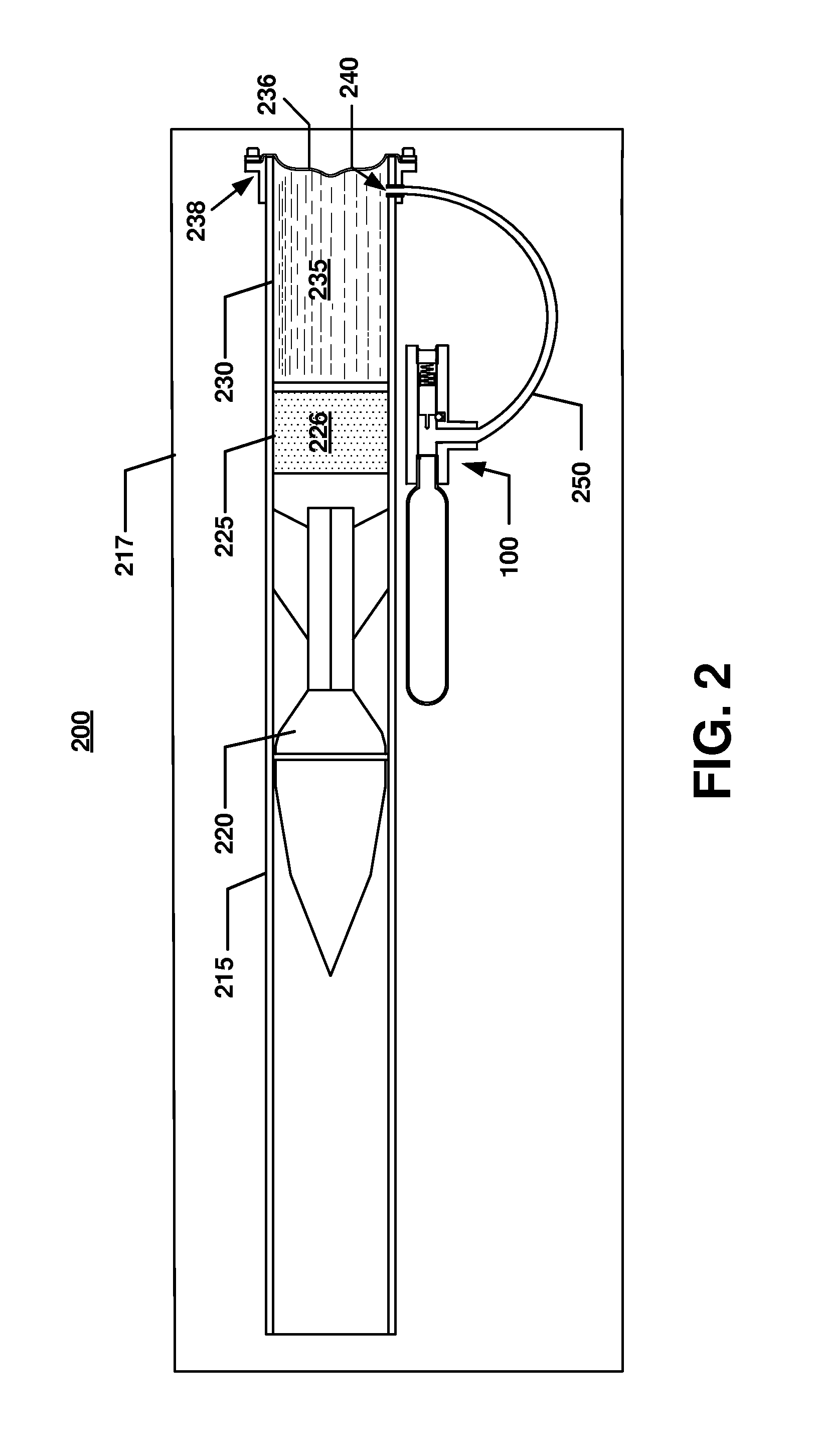
[0058]Wherefore, the present invention generally describes a novel bleeding mechanism 100 for use as an external auxiliary to an insensitive munition 200, for example as part of a storage unit or container 217, as illustrated in FIG. 2. Since the bleeding mechanism 100 is located externally relative to the barrel 215, it is...


PUM


Abstract

A bleeding mechanism for use in the propulsion system of a recoilless, insensitive munition utilizing a utilizing a fluidic countermass. The present bleeding mechanism utilizes a firing pin or a similar puncture or tear device. A heat sensitive material blocks the movement of the firing pin. A mechanical locking mechanism locks the firing pin in position until it is unlocked by the melting of the heat sensitive material. When the insensitive munition is exposed to heat, the reaction of the heat sensitive material within the bleeding mechanism allows the firing pin to be released and to rupture a cartridge seal. The cartridge may be filled with a compressed compound, which releases gas under pressure to the countermass container, causing a countermass cover to rupture, thereby emptying the countermass fluid.

Description

FEDERAL INTEREST STATEMENT[0001]The inventions described herein may be manufactured, used and licensed by the United States Government for United States Government purposes without payment of any royalties thereon or therefore.FIELD OF THE INVENTION[0002]The present invention relates in general to the field of weaponry. In particular, the present invention relates to a bleeding mechanism for use in the propulsion system of a recoilless, insensitive munition utilizing a fluidic countermass.BACKGROUND OF THE INVENTION[0003]The U.S. Department of Defense is currently moving toward the long-term goal of insensitive munition-compliant inventory. The acquisition treatment of insensitive munitions was the subject of a Jan. 26, 1999, memorandum from the Under Secretary of Defense for Acquisition, Technology and Logistics. The overall intent of the memorandum was to focus scarce resources on forward fit incorporation of insensitive munition-compliant technology.[0004]Insensitive munition is ...

Claims


Application Information

Patent Timeline
IPC IPC(8): F41A1/08
CPCF41A1/08F41A1/10F42B39/20
Inventor MOY, LEON
Owner UNITED STATES OF AMERICA THE AS REPRESENTED BY THE SEC OF THE ARMY
Learn More