Liquid distribution device

a technology of liquid distribution device and liquid storage container, which is applied in the direction of process and machine control, separation processes, instruments, etc., can solve the problems of deterioration of durability, increased consumption of compressed air, and reduced packing performance, and achieves simple structure, easy assembly, and easy maintenance

Active Publication Date: 2016-09-20
AMTPACIFIC
View PDF12 Cites 0 Cited by
  • Summary
  • Abstract
  • Description
  • Claims
  • Application Information

AI Technical Summary

Benefits of technology

[0021]The liquid distribution device according to the embodiment of the present invention is capable of continuously supplying the liquid at a constant ratio and of controlling the liquid in various ratios by automatically controlling the opening and closing of the valve.
[0022]According to the liquid distribution device according to the embodiment of the present invention, since a through-hole through which the supplied liquid passes is located at a predetermined height, the impurities in the liquid are not able to passes through the through-hole, so that it is possible to prevent the supply of the liquid from being stopped due to the impurities in the process of distributing the liquid at a constant ratio.
[0023]The liquid distribution device according to the embodiment of the present invention has a simple structure and is easy to assemble. Also, the liquid distribution device has no component to be consumed and is easy to maintain and reduces the cost and time for repair.

Problems solved by technology

Therefore, for a time during which the feeder rotates from one side to the other side, the liquid is not continuously supplied, so that surging occurs and the performance of packing is decreased.
Also, since compressed air consumption is increased and durability is deteriorated due to the continuous rotation of the axis, the main parts should be replaced after operation for a certain period of time.
However, a difference occurs between the actual time ratio and the distribution ratio, and thus, it is necessary to always correct in advance the difference by the liquid flow test.
Also, in the process of distributing the liquid for the purpose of supplying the liquid, impurities included in the liquid causes errors to occur in the operation of the liquid distribution device.

Method used


Image

  • Liquid distribution device
  • Liquid distribution device
  • Liquid distribution device

Examples


Embodiment Construction

[0029]The embodiment of the present invention will be described with reference to the accompanying drawings.

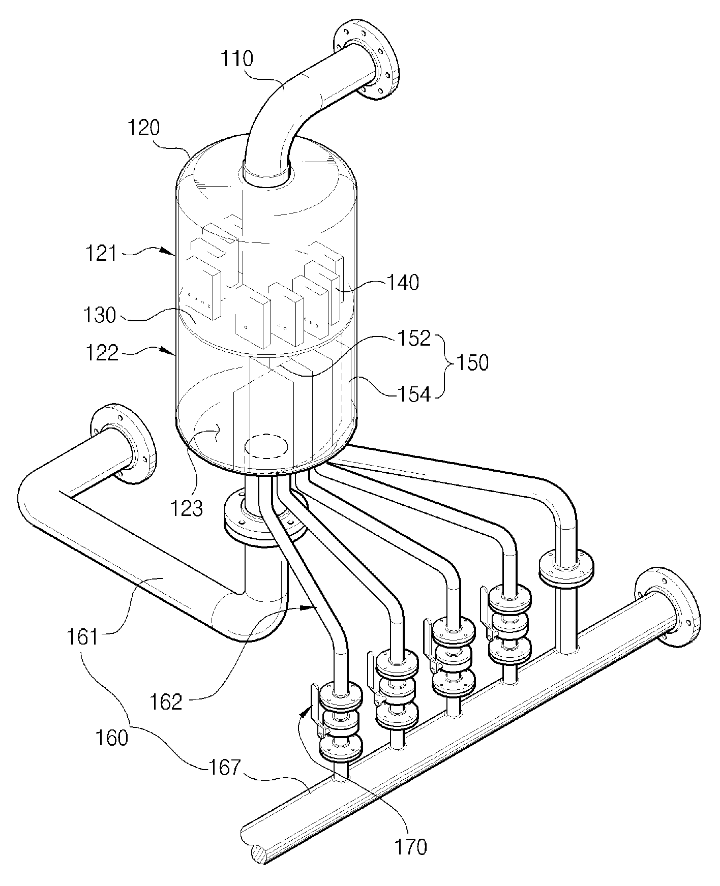
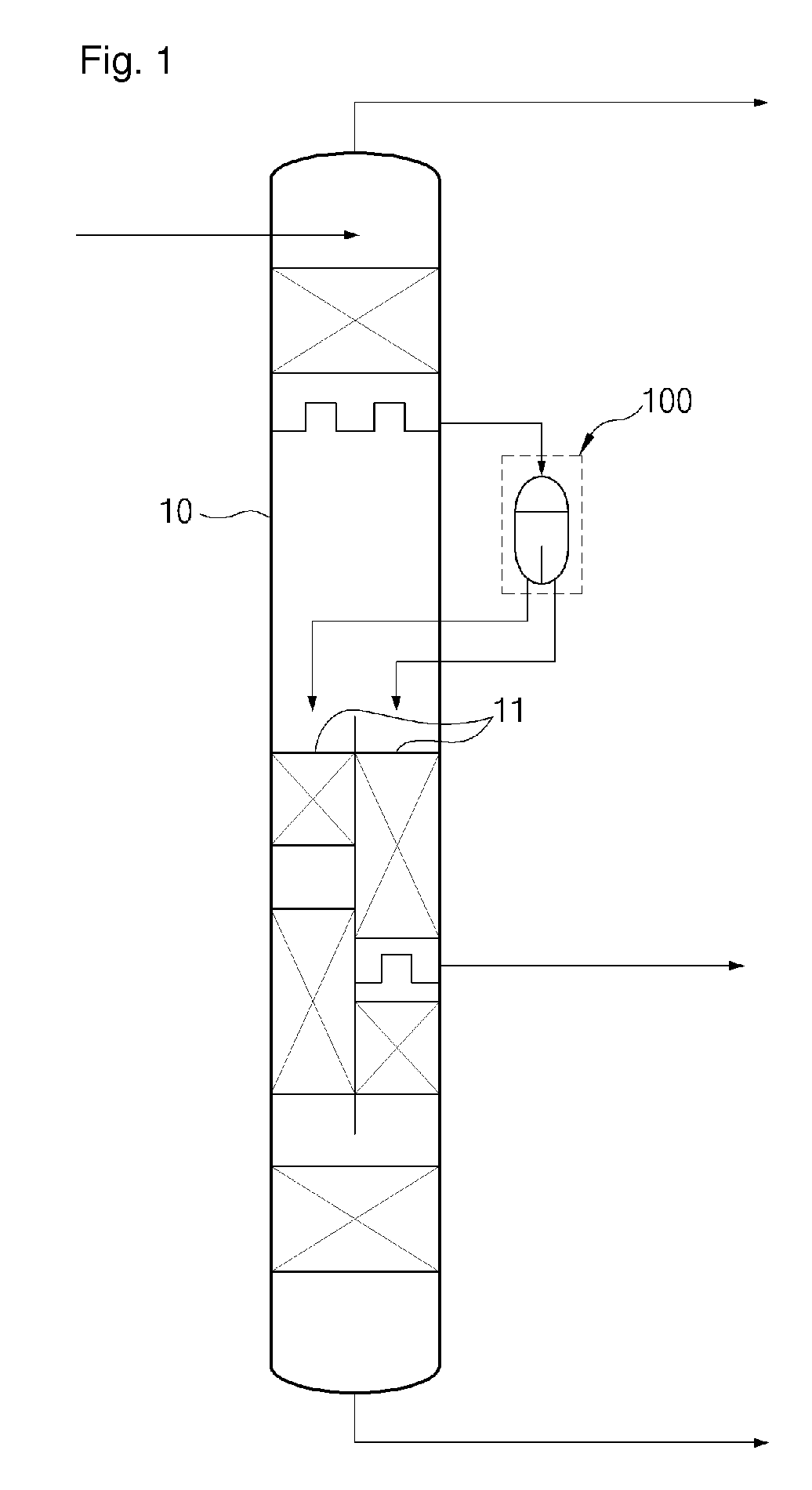
[0030]FIG. 1 is a schematic view of a divided wall column 10 including a liquid distribution device 100 according to the embodiment of the present invention. FIG. 2 is a perspective view showing the configuration of an example of the liquid distribution device 100 shown in FIG. 1.

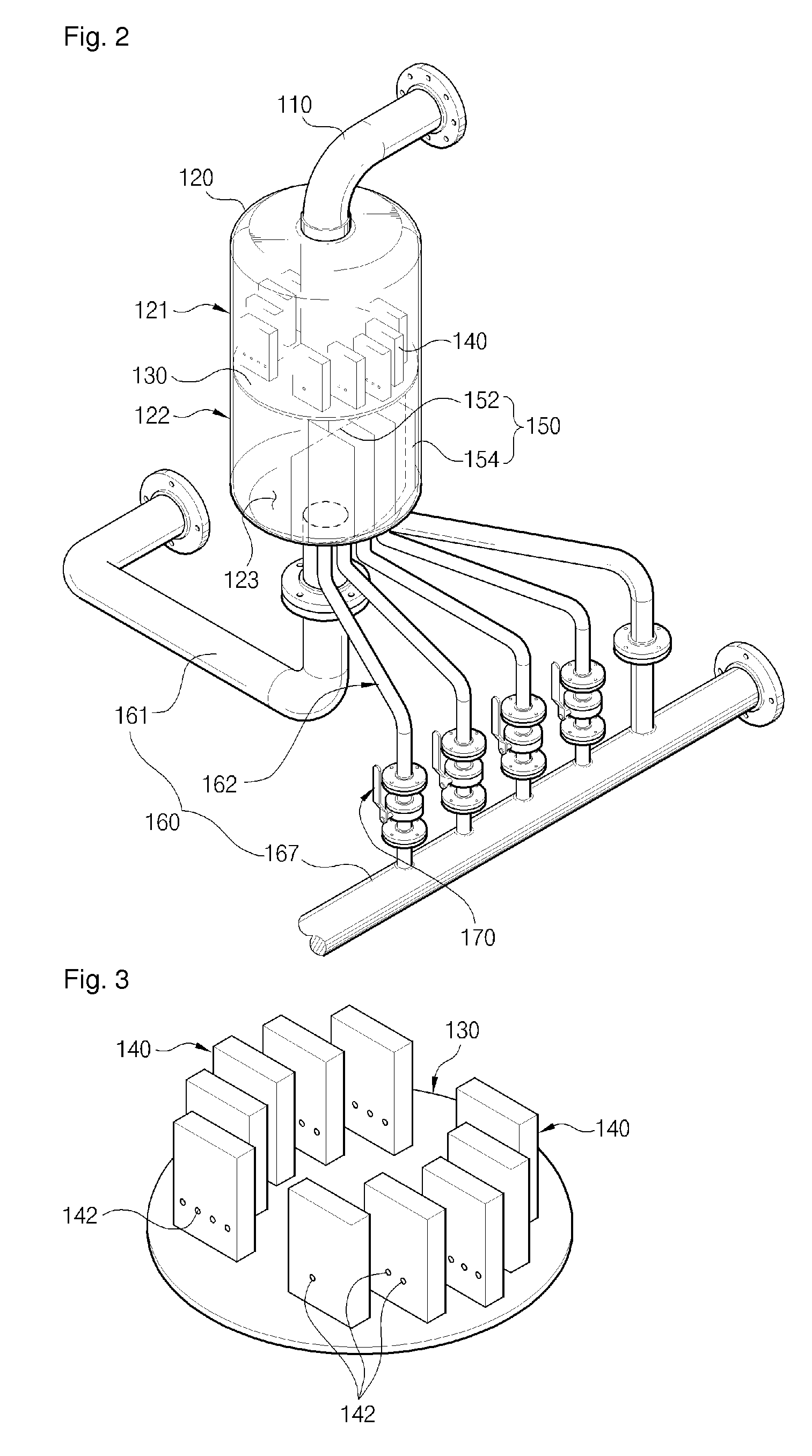
[0031]Referring to FIGS. 1 and 2, the liquid distribution device 100 includes a housing 120, a partition plate 130, a plurality of risers 140, partition walls 150 including a first partition wall 152 and a plurality of second partition wall 154, a plurality of outlets 160, and a valve 170.

[0032]The housing 120 has a cylindrical shape with a predetermined size and an inner space for distributing the received liquid. An inlet pipe 110 is connected to the upper portion of the housing 120 for the purpose of supplying the liquid, i.e., distribution target. The plurality of outlets 160 are connected to the ...


PUM


Abstract

The present invention is capable of precisely controlling a supply ratio of liquid and continuously supplying liquid at a constant rate by using partition plates for controlling the amount of liquid distribution.

Description

RELATED APPLICATIONS[0001]This application is a National Phase of PCT Patent Application No. PCT / KR2012 / 009863 having International filing date of Nov. 21, 2012, which claims the benefit of priority of Korean Patent Application No. 10-2012-0054191 filed on May 22, 2012. The contents of the above applications are all incorporated by reference as if fully set forth herein in their entirety.TECHNICAL FIELD[0002]The present invention relates to a liquid distribution device, and more particularly to a liquid distribution device capable of precisely controlling a supply ratio of liquid and continuously supplying the liquid at a constant ratio.BACKGROUND OF INVENTION[0003]In general, a liquid distribution device is used in petroleum refinery, petrochemistry and fine chemistry, and is used in a scrubber, an absorber, etc., which adopt the principles of distillation, absorption and cooling so as to remove harmful gases or organic matters.[0004]There is a column which is currently industriall...

Claims


Application Information

Patent Timeline
Patent Type & Authority Patents(United States)
IPC IPC(8): B01D3/14G05D11/00B01J4/02B01J4/00B01D53/18B01D3/00B67D7/78
CPCB01D3/141B01D3/008B01D53/185B01J4/005B01J4/008B01J4/02B67D7/78G05D11/003Y10T137/479Y10T137/4857Y10T137/85938Y10T137/86212Y10T137/87539Y10T137/87547Y10T137/87877B01D3/32B01J4/00B67D99/00
Inventor LEE, BYEONG KYEOMKIM, KWANG HYUN
Owner AMTPACIFIC
Why Eureka
Try Eureka