Separating device, an internal combustion engine and centrifugal separator assembly and a method of separating contaminants from crankcase gas

a technology of centrifugal separator and separator assembly, which is applied in the direction of machines/engines, centrifuges, separation processes, etc., can solve the problems of unfavorable crankcase gas flow, and pressure in the separation space surrounding the centrifugal rotor becoming lower than the pressure in the crankcas

Active Publication Date: 2016-09-27
ALFA LAVAL CORP AB
View PDF15 Cites 1 Cited by
  • Summary
  • Abstract
  • Description
  • Claims
  • Application Information

AI Technical Summary

Benefits of technology

[0010]An object of the invention is to minimize the above mentioned risk and provide a reliable drainage of the separated particles from the centrifugal separator.
[0012]In this way, the invention makes use of a reliable pressure difference created by a centrifugal rotor in operation. The centrifugal rotor will work as a centrifugal fan having a lower pressure at the gas inlet than the pressure in the separation space surrounding the centrifugal rotor. This pressure difference is utilized to drain the separated particles into the collector. A small fraction of cleaned gas can hereby circulate through the particle outlet and back to the gas inlet, via the collector, to effectively draw the separated particles out through the particle outlet and into the collector. Consequently, instead of the previously mentioned gas flow from the particle outlet to the crankcase, the invention can provide a circulating gas flow from the particle outlet to the gas inlet of the centrifugal separator. A more reliable drainage of separated particles is hereby achieved, and the risk of contaminating the cleaned gas in the separation space is reduced.
[0015]In a further embodiment of the invention, the separator inside the collector is configured as a baffle separator. The baffles may for example form a labyrinth path by means of which the separated particles are collected inside the collector and thereby prevented from being transferred to the gas inlet.
[0018]In a further embodiment of the invention, there is a conduit which is arranged to conduct the separated particles from the collector to the crankcase, and the conduit includes a discharge end which is situated below an oil level in the crankcase. A liquid (oil) trap is thereby formed inside the crankcase which prevents the crankcase gas (oil mist) therein to flow the wrong way, i.e. from the crankcase via the conduit to the collector, or even further into the centrifugal separator.

Problems solved by technology

There is a risk however that the pressure in the separation space surrounding the centrifugal rotor becomes lower than the pressure in the crankcase.
This results in an undesired pressure difference, between the separation space and the crankcase, which counteracts or prevents the flow of separated particles to the crankcase.
It may even cause an undesired flow of crankcase gas to the centrifugal separator via the particle outlet.
The improper drainage of separated particles will eventually lead to contamination of the cleaned gas inside the separation space surrounding the centrifugal rotor.

Method used


Image

  • Separating device, an internal combustion engine and centrifugal separator assembly and a method of separating contaminants from crankcase gas
  • Separating device, an internal combustion engine and centrifugal separator assembly and a method of separating contaminants from crankcase gas
  • Separating device, an internal combustion engine and centrifugal separator assembly and a method of separating contaminants from crankcase gas

Examples


Embodiment Construction

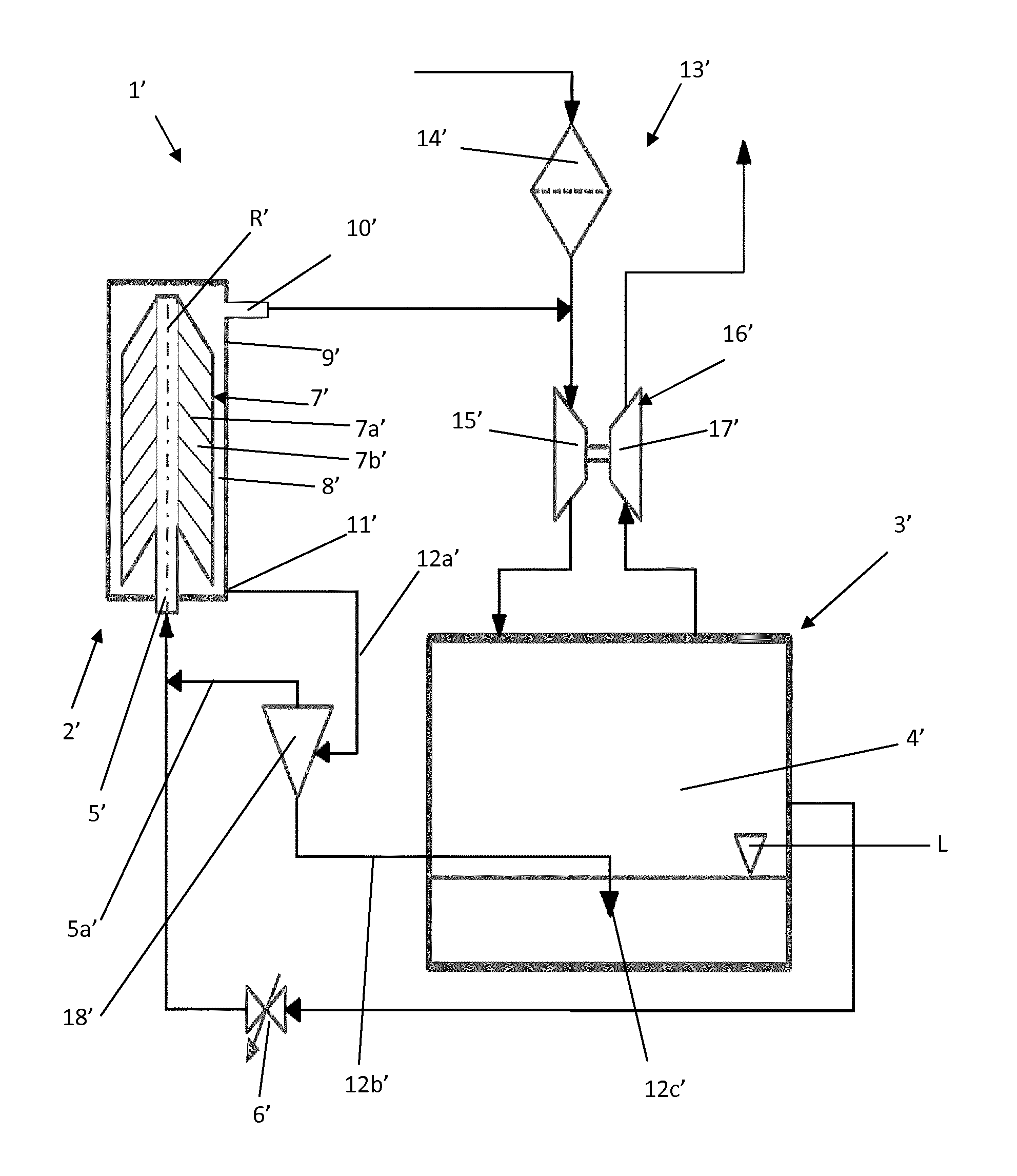
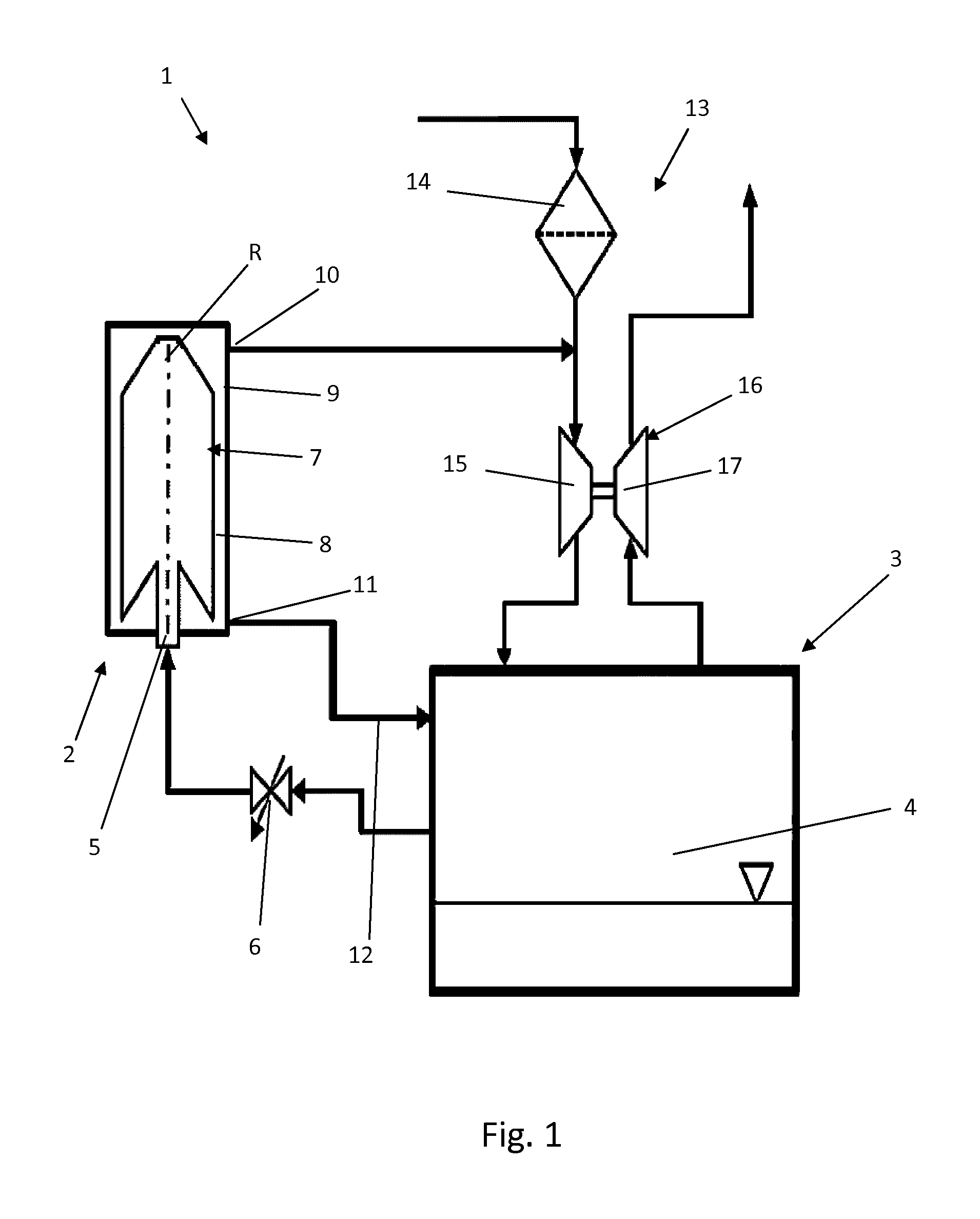
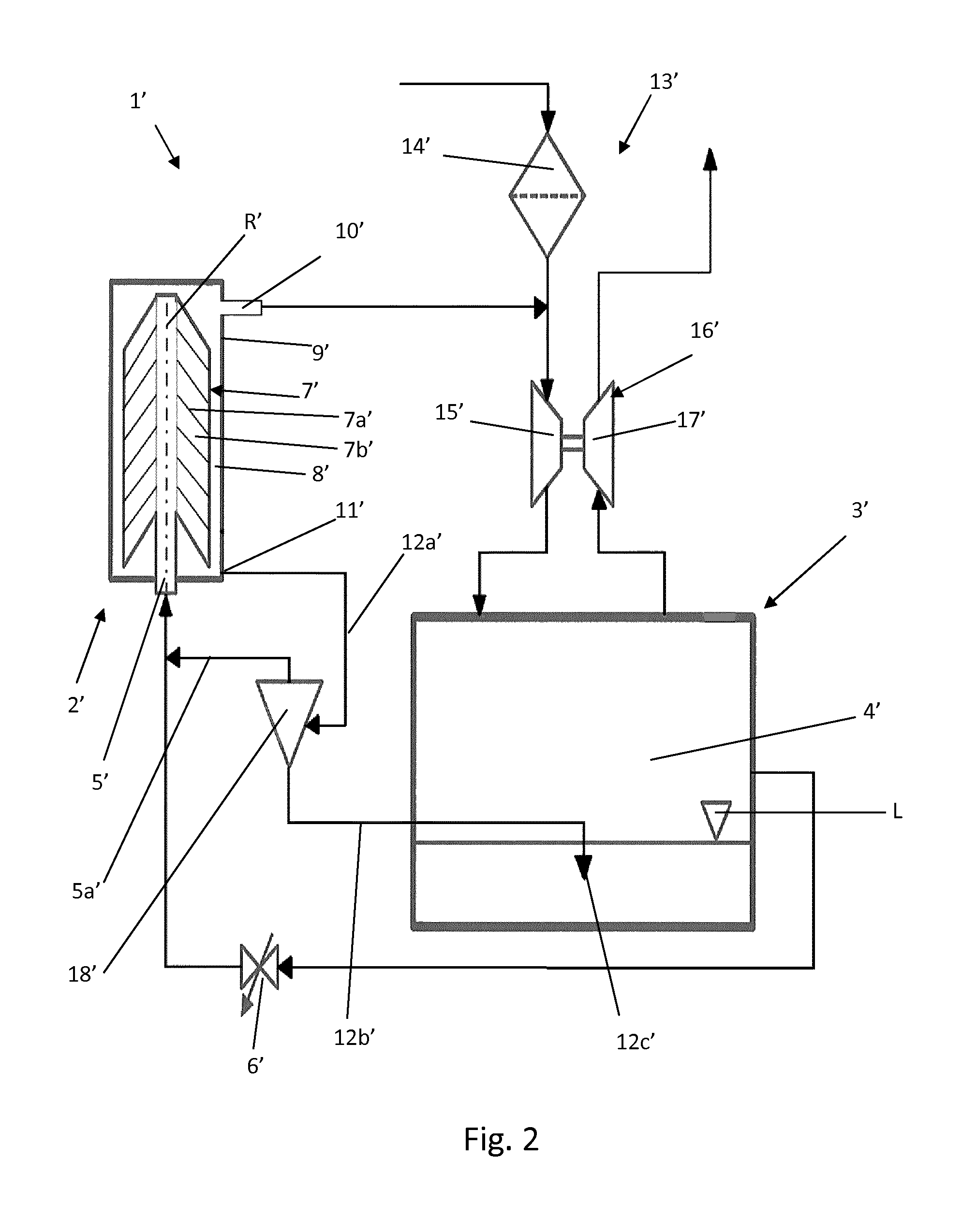
[0029]FIG. 1 shows an internal combustion engine and a centrifugal separator assembly 1. Hence, a centrifugal separator 2 is arranged to a combustion engine 3 having a crankcase 4 which is configured to ventilate contaminated crankcase gas through the centrifugal separator 2. As can be seen the crankcase 4 is connected to a gas inlet 5 of the centrifugal separator 2 via a regulating valve 6 which is arranged to maintain a desired gas pressure in the crankcase 4 during different running conditions for the combustion engine 3 (e.g. different load and speed conditions giving different blow-by flow rates).

[0030]The centrifugal separator 2 is arranged for separating contaminants in the form of oil mist and soot particles from the crankcase gas by means of a centrifugal rotor 7 with a plurality of separation discs (not shown). The centrifugal rotor 7 is arranged to rotate about a rotational axis R in a separation space 8 inside a rotor housing 9.

[0031]As can be seen the rotor housing 9 is...


PUM

PropertyMeasurementUnit
pressureaaaaaaaaaa
heightaaaaaaaaaa
hydrostatic pressureaaaaaaaaaa

Abstract

An internal combustion engine and centrifugal separator assembly separates contaminants from crankcase gas. A crankcase is connected to the centrifugal separator including a centrifugal rotor. A rotor housing delimits a separation space in which the centrifugal rotor is arranged to rotate. A gas inlet conducts crankcase gas to a central part of the centrifugal rotor. A gas outlet communicates with a part of the separation space surrounding the centrifugal rotor and to conduct cleaned crankcase gas out of the separation space. A particle outlet communicates with the part of the separation space. The particle outlet is connected to a collector for the separated particles. The collector is configured to communicate with the gas inlet via a connection to provide a pressure difference between the particle outlet and the collector. The separated particles are drawn out of the particle outlet and into the collector during operation of the centrifugal separator.

Description

TECHNICAL FIELD[0001]The invention relates to a separating device for separating contaminants in the form of liquid and / or solid particles from crankcase gas which is produced during operation of an internal combustion engine according to the preamble of claim 1.[0002]The invention also relates to an internal combustion engine and centrifugal separator assembly for separating contaminants in the form of liquid and / or solid particles from crankcase gas which is produced during operation of the engine according to the preamble of claim 5.[0003]The invention furthermore relates to a method of separating contaminants in the form of liquid and / or solid particles in crankcase gas which is produced during operation of an internal combustion engine according to the preamble of claim 14.BACKGROUND ART[0004]FIG. 1 discloses an internal combustion engine and centrifugal separator assembly for separating contaminants in the form of liquid and / or solid particles from crankcase gas which is produ...

Claims


Application Information

Patent Timeline
Patent Type & Authority Patents(United States)
IPC IPC(8): B01D45/00B04B5/10B04B11/02B04B5/12B01D21/26B01D45/14B04B5/08F01M13/04
CPCB04B5/08B01D21/262B01D45/14B04B5/10B04B5/12B04B11/02F01M13/04B04B2005/125F01M2013/0422F01M2013/0488
Inventor TORNBLOM, OLLE
Owner ALFA LAVAL CORP AB
Why Eureka
Try Eureka