Electromagnetic relief valve for turbocharger

a technology of electromagnetic relief valve and turbocharger, which is applied in the direction of valve housing, magnetic body, machine/engine, etc., can solve the problems of increased leakage, high production cost, unstable operation of the valve, and complex processing and installation of manufacturing, so as to simplify the structure of the relief valve and increase the magnetic area , the effect of easy assembly

Inactive Publication Date: 2016-09-27
WANG YAOTING
View PDF6 Cites 4 Cited by
  • Summary
  • Abstract
  • Description
  • Claims
  • Application Information

AI Technical Summary

Benefits of technology

[0007]To solve the above problems, the invention provides a new electromagnetic relief valve for turbocharger, which simplifies the structure and effectively increases the magnetic force of the pressure relief valve for a more uniform magnetic force line in the whole actuation process.

Problems solved by technology

1. The guide pin results in complex processing and installation in manufacturing, high production costs and unstable operations of the valve.
2. The electromagnetic relief valve for turbocharger is usually provided with a seal cover. The existing seal cover is plastically molded. It is relatively rigid and easy to become deformed after long period of application under high temperature, resulting in a greater leakage, which is difficult to control for rapid pressurization or depressurization.
3. Lathing method is usually applied in prior art to produce the V-shaped seal ring with high temperature resistance. The disadvantages of this approach are as follows: on one hand, it needs precision lathes and other expensive manufacturing equipment, and on the other hand, lathing method requires stricter purity of bar materials, resulting in the poor performance of the V-shaped ring with high temperature resistance. In prior art, the method of injection molding for production of the V-shaped ring with high temperature resistance also has corresponding problems. It proposes high requirements for the molds. And a long period of application under high or low temperature will result in serious deformation, therefore, it is difficult to control its sealing performance, and the leakage is not easy to reach the standard requirement.

Method used


Image

  • Electromagnetic relief valve for turbocharger
  • Electromagnetic relief valve for turbocharger
  • Electromagnetic relief valve for turbocharger

Examples


Embodiment Construction

[0031]The technical scheme of the embodiments of the invention will be described clearly and completely in combination with the drawings of the embodiments of the invention.

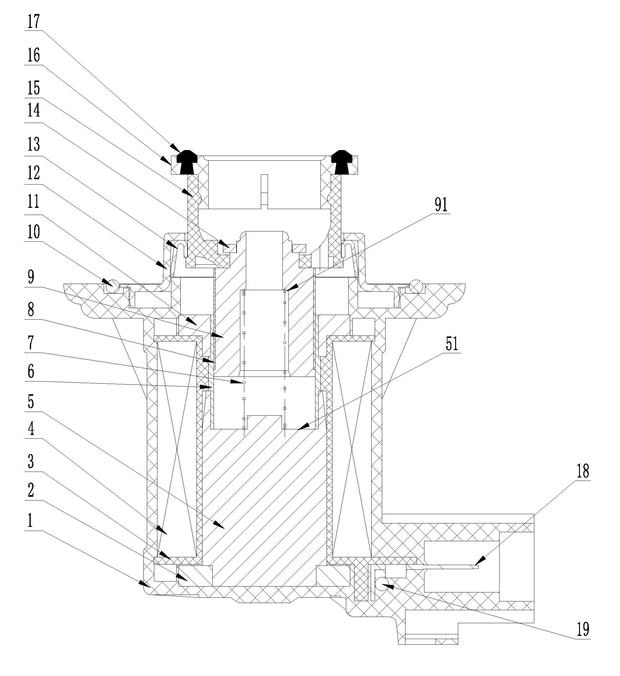
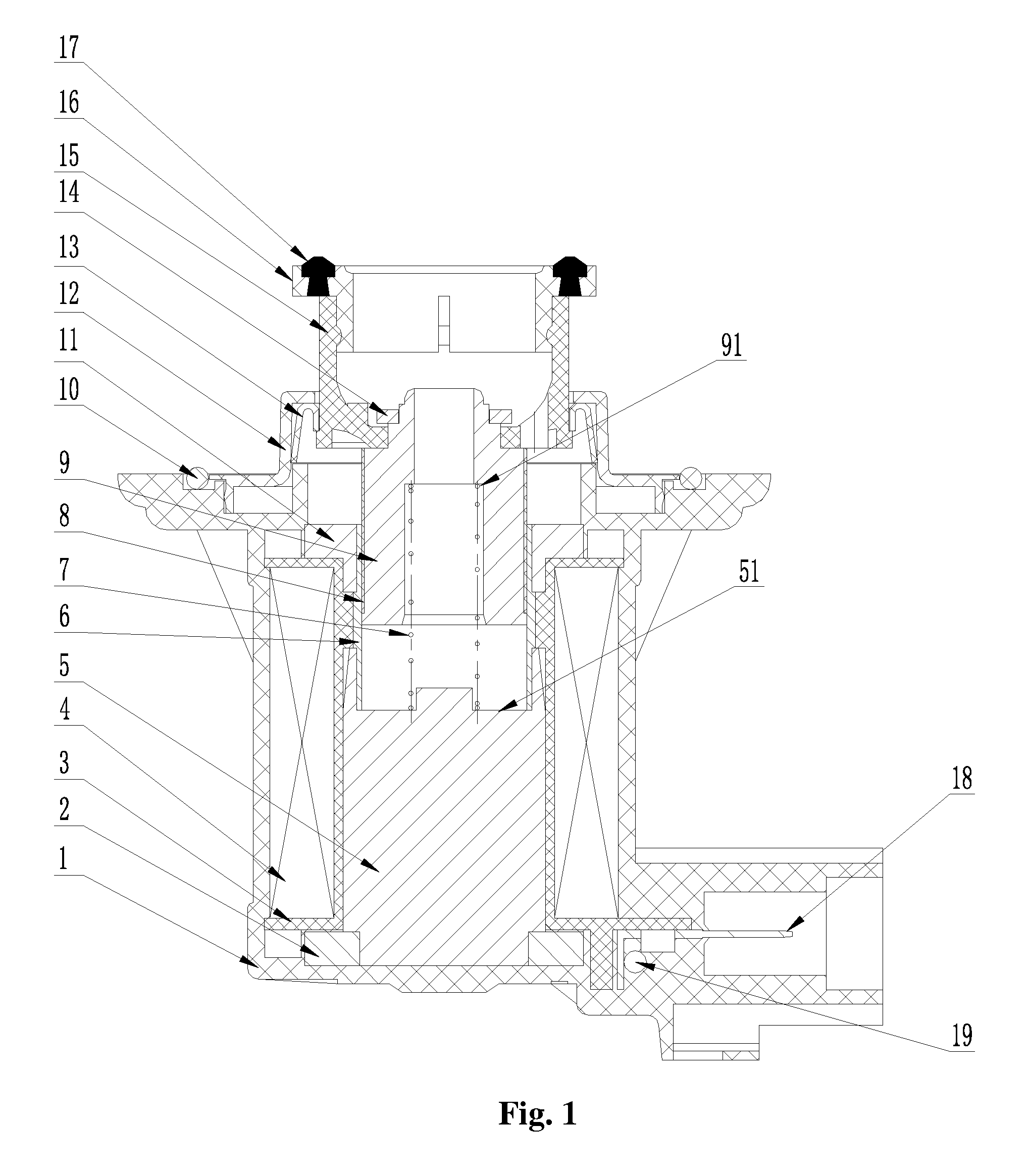
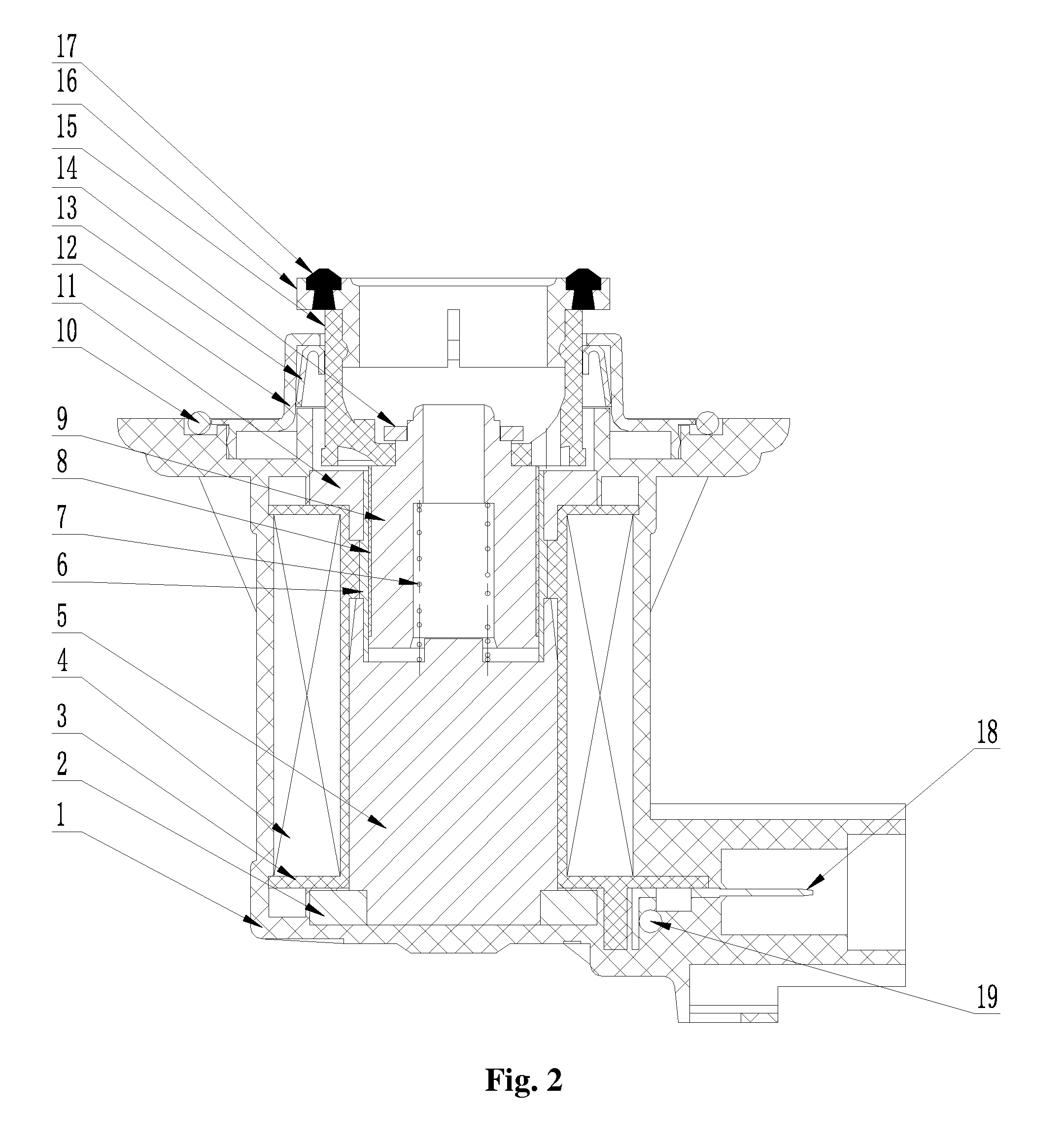
[0032]As shown in FIG. 1, a new electromagnetic relief valve for turbocharger in the embodiment comprises a high-temperature-resistant plastic valve body 1 with an electronic element resistor 19 and a connecting copper piece 18, wherein, the valve body 1 seals the electromagnetic bonnet 12 by an O-shaped seal ring 10, the bottom of the valve body 1 is provided with a static core 5, the periphery of the bottom of the static core 5 is provided with a magnetic conductive disc 2, the upper part of the magnetic conductive disc 2 is provided with a coil holder 3 and the coil holder 3 is provided with a coil winding 4 wrapped around the periphery of the static core 5.

[0033]The top of the valve body 1 is provided with a dynamic core 9 corresponding to the static core 5, a compressed spring 7 is provided between the dynam...


PUM

PropertyMeasurementUnit
magnetic conductiveaaaaaaaaaa
heightaaaaaaaaaa
depthaaaaaaaaaa

Abstract

An electromagnetic relief valve for turbocharger includes a valve body and an electromagnetic bonnet. The bottom of the valve body is provided with a static core, the periphery of the static core is provided with a magnetic conductive disc, the top of the magnetic conductive disc is provided with a coil holder, which is provided with a coil winding wrapped around the periphery of the static core. The top of the valve body is provided with a dynamic core corresponding to the static core, a compressed spring is provided between the dynamic core and the static core, and the exterior of the dynamic core is provided with a sliding bearing and the periphery of the dynamic core is provided with an integrated magnetic cover with a magnetic ring matched with the magnetic conductive disc. The relief valve actuates and forms a more uniform magnetic force line.

Description

CROSS-REFERENCE TO RELATED APPLICATIONS[0001]This present application claims the benefit of Chinese Patent Application No. 201510039845.6 filed on Jan. 26, 2015, the contents of which are hereby incorporated by reference.FIELD OF THE INVENTION[0002]The invention relates to a turbocharger component, in particular to a new electromagnetic relief valve for turbocharger.BACKGROUND OF THE INVENTION[0003]Currently, the turbocharging technology is becoming more and more popular for its capacity of effectively enhancing the efficiency of the engine. It has become one of the main trends for energy saving and environmental protection in the gasoline energy times. At present, a lot of electromagnetic valves are widely applied in the field of turbocharged engines. However, most electromagnetic valves existing in the market include an electromagnetic circuit comprising a coil winding wrapped around the coil holder, a static core, a dynamic core, a magnetic conductive disc and a magnetic cover, e...

Claims


Application Information

Patent Timeline
Patent Type & Authority Patents(United States)
IPC IPC(8): F16K31/06H01F7/121H01F7/08F16K17/00
CPCF16K31/0675F16K17/00H01F7/081H01F7/121F16K27/029F16K31/0655F01D17/105F02B37/12F02B39/00F05D2220/40F05D2270/62F05D2300/507
Inventor WANG, YAOTING
Owner WANG YAOTING
Why Eureka
Try Eureka