Corona discharge device and air-conditioning apparatus

a discharge device and air-conditioning technology, applied in lighting and heating apparatus, vapor flow control, heating types, etc., can solve problems such as local discharge and disconnection, and achieve the effect of convenient assembly and high charging efficiency

Active Publication Date: 2016-10-04
MITSUBISHI ELECTRIC CORP
View PDF20 Cites 20 Cited by
  • Summary
  • Abstract
  • Description
  • Claims
  • Application Information

AI Technical Summary

Benefits of technology

[0011]The corona discharge device according to the present invention has high charging efficiency, and facilitates assembly of the first discharge electrodes and the counter electrodes.

Problems solved by technology

However, when the thin wires are used, local discharge and disconnection may be caused by, for example, corrosion or sputtering.

Method used


Image

  • Corona discharge device and air-conditioning apparatus
  • Corona discharge device and air-conditioning apparatus
  • Corona discharge device and air-conditioning apparatus

Examples


embodiment 1

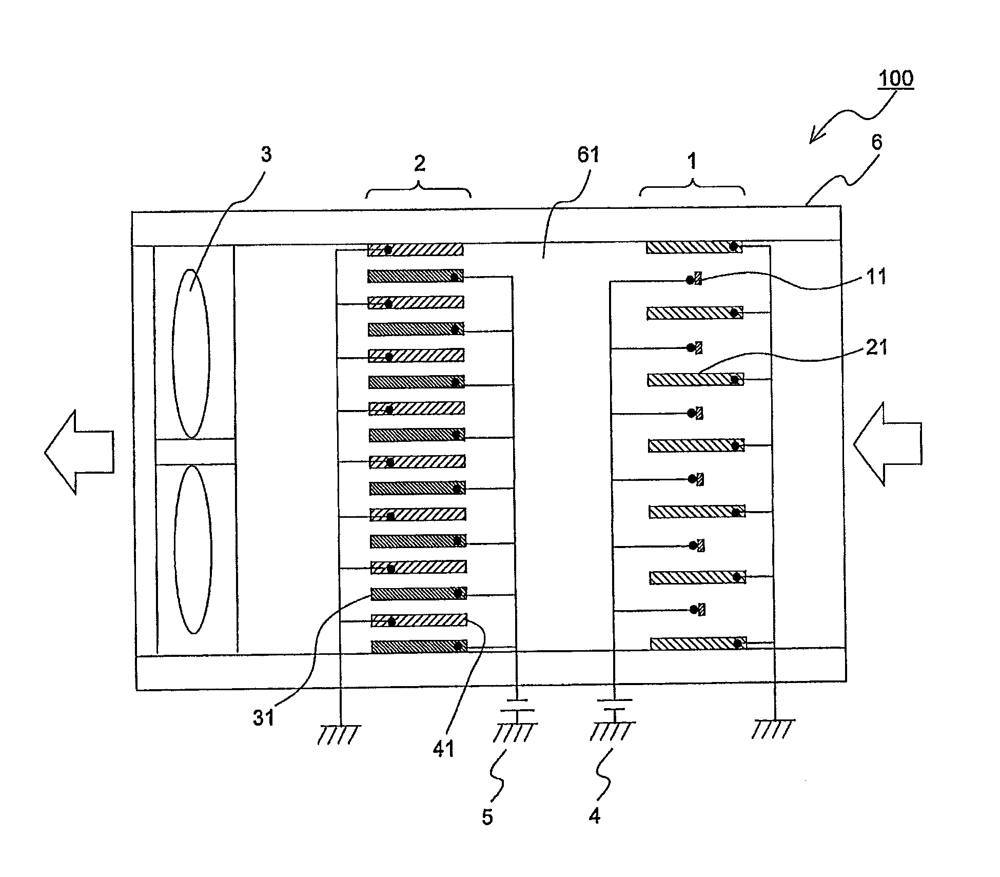
[0041]FIG. 1 is a schematic view of a corona discharge device (hereinafter referred to as a device 100) according to Embodiment 1. With reference to FIG. 1, the structure and operation of the device 100 will be described. In FIG. 1 and subsequent drawings, the dimensional relationships among components are sometimes different from the actual ones. Further, in FIG. 1, the flow of air is shown by arrows.

[Device 100]

[0042]The device 100 is an electric dust collection device that cleans the space by capturing particles (hereinafter referred to as suspended particles) and microbes and viruses (hereinafter suspended microbes) that are suspended in air flowing in the device 100 and supplying the air to the outside after the suspended particles and suspended microbes are captured from the air. The device 100 includes an air-path housing 6 having therein an air path 61 through which air flows. In the air path 61, a charging section 1, a capturing section 2, and a fan 3 are disposed.

[0043]The...

embodiment 2

[0071]While the single charging-section ground electrode unit 20 is provided in Embodiment 1 described above, a description will be given of Embodiment 2 in which a plurality of charging-section ground electrode units 20 are provided. Another structure example of charging-section ground electrodes according to Embodiment 2 will be described with a focus on differences from Embodiment 1. Embodiment 2 can be combined with Embodiments described below.

[0072]FIG. 7 is an exploded perspective view illustrating a structure of a charging section according to Embodiment 2. As illustrated in FIG. 7, a charging section 1 includes two charging-section ground electrode units 20 (sometimes distinctively referred to as a charging-section ground electrode unit 20a and a charging-section ground electrode unit 20b). The charging-section ground electrode unit 20a and the charging-section ground electrode unit 20b are superposed such that charging-section ground electrodes 21 of the charging-section gr...

embodiment 3

[0087]Embodiment 3 will be described with a focus on differences of another exemplary structure of a charging section from that adopted in Embodiment 1. Embodiment 3 can be combined with Embodiments described below.

[0088]FIG. 11 is a rear view of a charging-section high-voltage electrode unit according to Embodiment 3.

[0089]In Embodiment 1 illustrated in FIG. 6, the support portions 12 provided on the charging-section high-voltage electrode unit 10 are attached to the frame member 62 with the insulators 7 being disposed therebetween. In Embodiment 3, a charging-section high-voltage electrode unit 10 is assembled without forming support portions 12 and insulators 7. As illustrated in FIG. 11, the charging-section high-voltage electrode unit 10 is attached to be superposed on an insulating body 8 shaped like a frame-shaped rectangular flat plate. The width and height dimensions of the rectangular frame shape of the insulating body 8 are large enough to include a frame portion 13 of th...


PUM

PropertyMeasurementUnit
thicknessaaaaaaaaaa
diameteraaaaaaaaaa
thicknessaaaaaaaaaa

Abstract

A corona discharge device includes a charging-section high-voltage electrode unit including a plurality of charging-section high-voltage electrodes, and a charging-section ground electrode unit includes a plurality of charging-section ground electrodes formed by flat plates. The plurality of charging-section high-voltage electrodes are arranged at intervals in a direction intersecting an airflow in an air path, and are connected to one another at at least one longitudinal end by a conductive frame portion. The plurality of charging-section ground electrodes are disposed between the charging-section high-voltage electrodes in an orientation such that flat surfaces thereof are substantially parallel to the airflow in the air path, and are connected at at least one longitudinal end by a conductive frame portion. The plurality of charging-section high-voltage electrodes and the plurality of charging-section ground electrodes are alternately stacked in the direction intersecting the airflow in the air path to be spaced apart from each other.

Description

TECHNICAL FIELD[0001]The present invention relates to a corona discharge device for use in an electric dust collection device, a deodorization device, a sterilization device, a virus removing device, and so on, and to an air-conditioning apparatus including this corona discharge device.BACKGROUND ART[0002]Conventionally, electric dust collection devices and deodorization devices adopt a technique of providing a corona discharge unit for bringing dust into a charged state by corona discharge and capturing the charged dust by a dust collector. In general, this corona discharge unit is configured to apply high voltage to discharge electrodes formed by wire electrodes having a wire diameter of about 0.1 mm to 1.0 mm so as to generate corona discharge between the discharge electrodes and counter electrodes. The thinner the used wire electrodes are, the lower the applied voltage for generating discharge can be. However, when the thin wires are used, local discharge and disconnection may b...

Claims


Application Information

Patent Timeline
Patent Type & Authority Patents(United States)
IPC IPC(8): A62B7/08B03C3/09A61L9/00B03C3/36B03C3/47F24F3/16A61L2/00B03C3/41A61L9/16B03C3/12F24F8/10
CPCA61L9/16A61L2/00A61L9/00B03C3/09B03C3/12B03C3/368B03C3/41B03C3/47F24F3/1603F24F3/166F24F2003/1635F24F2003/1682A61L9/22F24F8/30F24F8/192Y02A50/20F24F8/10F24F8/194
Inventor OTA, KOJIINANAGA, YASUTAKAMORIKAWA, AKIRASAKAI, TAKAHIROTANIMURA, YASUHIRO
Owner MITSUBISHI ELECTRIC CORP
Why Eureka
Try Eureka