Hydraulic fracturing system
a technology of hydraulic fracturing and hydraulic fracturing, which is applied in the direction of fluid removal, chemistry apparatus and processes, borehole/well accessories, etc., to achieve the effect of increasing the injection ra
- Summary
- Abstract
- Description
- Claims
- Application Information
AI Technical Summary
Benefits of technology
Problems solved by technology
Method used
Image
Examples
example 1
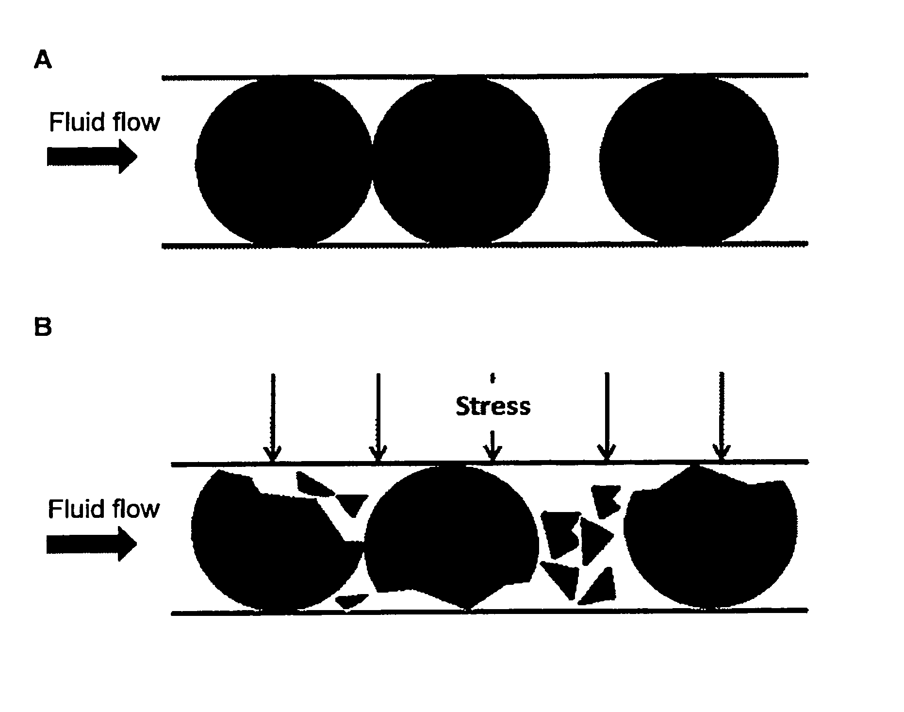
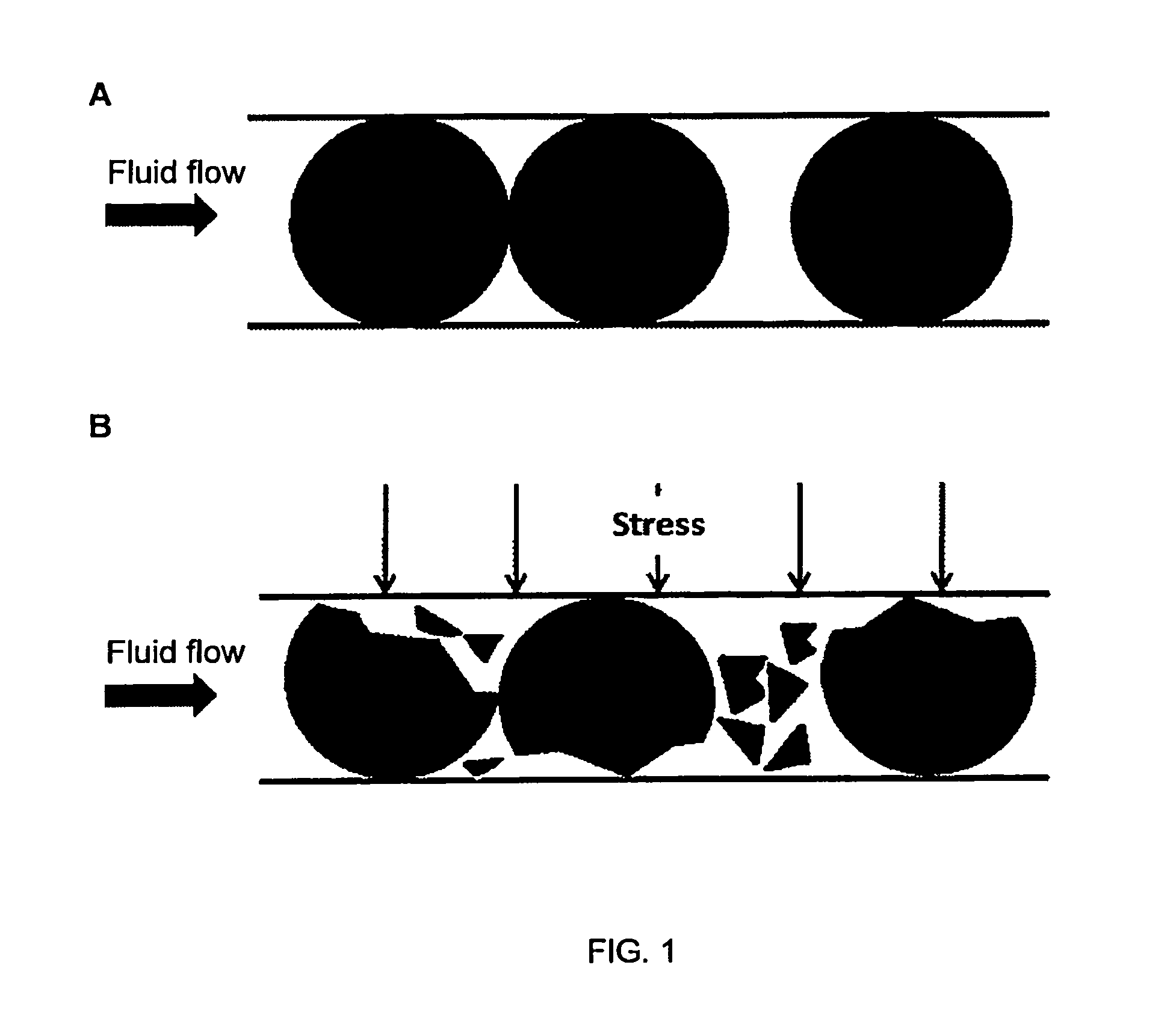
[0040]A tube with a fixed inner diameter is filled with fragile spherical proppant particles having nearly the same diameter as the tube (see FIG. 1A). In this case, before closure stress is applied, the tube will have almost zero permeability; even though the total porosity of the pack might be quite high, the porosity available for fluid flow is negligible. Once an external closure stress is applied, and the inner diameter is reduced, the proppant particles start crushing (FIG. 1B), the total pack volume decreases and so does the total pack porosity. However, the proppant crushing leads to opening of pore space and the relative effective porosity (which is a fraction of the total porosity) increases, which results in an increase in the tube permeability.
example 2
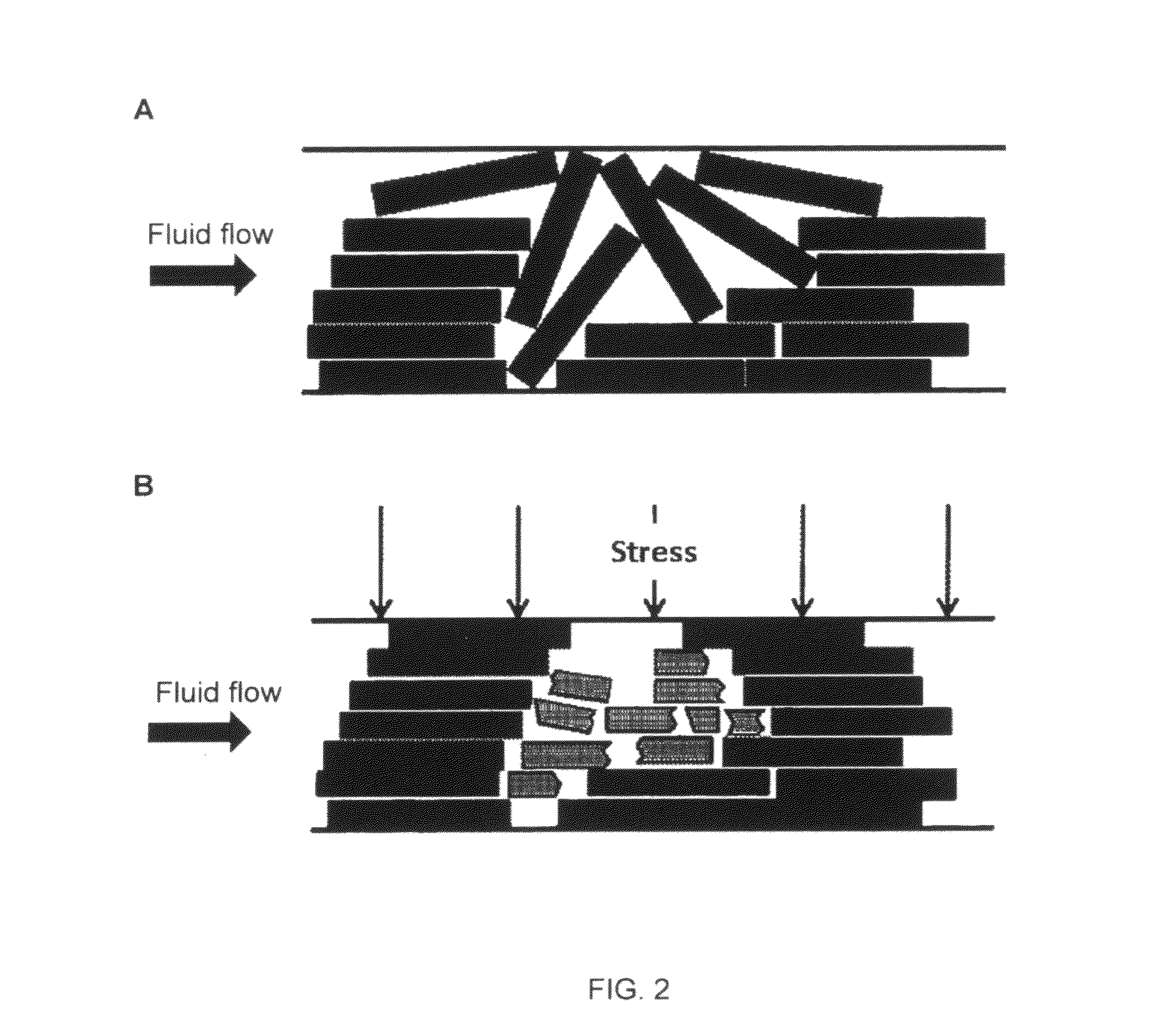
[0041]For non-spherically shaped materials, for example plates, this effect can be even more pronounced, as the conditions in this latter case are much closer to those encountered in the field, as compared to those in the first example. Consider non-spherical particles, for example plates, in a fracture having parallel walls. Without any externally applied stress, the particles are oriented randomly (except perhaps for some orientation induced by transport fluid flow) and a substantial fraction of the pack porosity is confined (see FIG. 2A). Once the stress is applied, the particles tend to align with the walls and some of them are crushed, opening flow channels (see FIG. 2B). The effect of closure stress on the permeability of the pack therefore may be quite complicated, and permeability and effective porosity generally can increase with closure stress applied on the pack. A similar result can be obtained with rods and / or cylinders.
Laboratory Experiments
Materials
[0042]A commercial ...
example 3
[0046]The conductivities of muscovite mica MD250 packs at proppant loadings of 2.44 and 9.77 kg / m2 were measured with the standard conductivity apparatus, while special precautions were taken to avoid parasitic flows due to the low proppant pack permeabilities. (Compared to conventional proppant packs, the packs of plate-like mica particles were characterized by very low conductivities and by non-conventional stress distributions in the packs. Ohio sandstone cores are usually used for API conductivity tests; however, in our case flows through such cores were possible, which would have strongly affected conductivity results. Other parasitic flows might have existed due to unusually high pressure drops in the cells (up to 1.72 MPa (250 psi)), e.g. flows along the conductivity cell walls. Other challenges in conductivity measurements of mica packs have been faced. Special precautions used included: a) utilization of aluminum cores instead of sandstone ones; b) sealing the core edges wi...
PUM
| Property | Measurement | Unit |
|---|---|---|
| weight percent | aaaaa | aaaaa |
| aspect ratio | aaaaa | aaaaa |
| length | aaaaa | aaaaa |
Abstract
Description
Claims
Application Information
 - R&D
- Intellectual Property
- Life Sciences
- Materials
- Tech Scout
- Unparalleled Data Quality
- Higher Quality Content
- 60% Fewer Hallucinations
Browse by: Latest US Patents, China's latest patents, Technical Efficacy Thesaurus, Application Domain, Technology Topic, Popular Technical Reports.
© 2025 PatSnap. All rights reserved.Legal|Privacy policy|Modern Slavery Act Transparency Statement|Sitemap|About US| Contact US: help@patsnap.com


