Vacuum insulation material, insulation case unit, and refrigerator

a vacuum insulation material and insulation case technology, applied in the direction of insulation for cooling apparatus, domestic cooling apparatus, lighting and heating apparatus, etc., can solve the problems of insufficient restraint of the encapsulator (sheathing material), insulation material not being able to achieve desired insulation performance, and insulation material not being able to achieve the desired insulation performance. , to achieve the effect of excellent bending formability

Inactive Publication Date: 2016-10-11
SAMSUNG ELECTRONICS CO LTD
View PDF9 Cites 12 Cited by
  • Summary
  • Abstract
  • Description
  • Claims
  • Application Information

AI Technical Summary

Benefits of technology

[0010]It is an aspect of the present disclosure to provide a vacuum insulation material having excellent bending formability while restraining reduction in a gas barrier property of a sheathing material and an apparatus for keeping warm and cool using the same.

Problems solved by technology

In the vacuum insulation material disclosed in Japanese Patent Application Publication No. 2007-155065, however, elongation of the encapsulator (sheathing material) is not sufficiently restrained when the insulation material is bent along the grooves.
In this case, the sheathing material is damaged with the result that a gas barrier property is lowered and thus desired insulation performance may not be obtained.
However, in a case in which the vacuum insulation material is bent in the shape of an R (R bending), i.e. in a case in which the vacuum insulation material is bent such that a bendable region of the vacuum insulation material forms a curve having a predetermined radius of curvature, the vacuum insulation material does not sufficiently follow the curve with the result that a plurality of wrinkles are formed at the vacuum insulation material and thus insulation performance of the vacuum insulation material may be lowered.

Method used


Image

  • Vacuum insulation material, insulation case unit, and refrigerator
  • Vacuum insulation material, insulation case unit, and refrigerator
  • Vacuum insulation material, insulation case unit, and refrigerator

Examples


second concrete example

[0083]A plate-shaped sheathing material having no grooves is manufactured using the above manufacturing method. The sheathing material 3 is a laminate film obtained by coupling a polyamide film having a thickness of 25 μm an aluminum (about 50 nm)-deposited polyethylene terephthalate film having a thickness of 25 μm an aluminum foil having a thickness of 6 μm and a high-density polyethylene film having a thickness of 50 μm using dry lamination. A short fiber glass wool stack having an average fiber diameter of about 4 μm is used as the core 5. An adsorbent is omitted in consideration of measurement.

[0084]The vacuum insulation material 1 according to this concrete example may be manufactured by forming a plurality of grooves at the vacuum insulation material after the vacuum insulation material is formed. That is, an example of a manufacturing process of the vacuum insulation material 1 using the manufacturing method described in this embodiment is as follows. FIG. 10 is a sectional ...

third concrete example

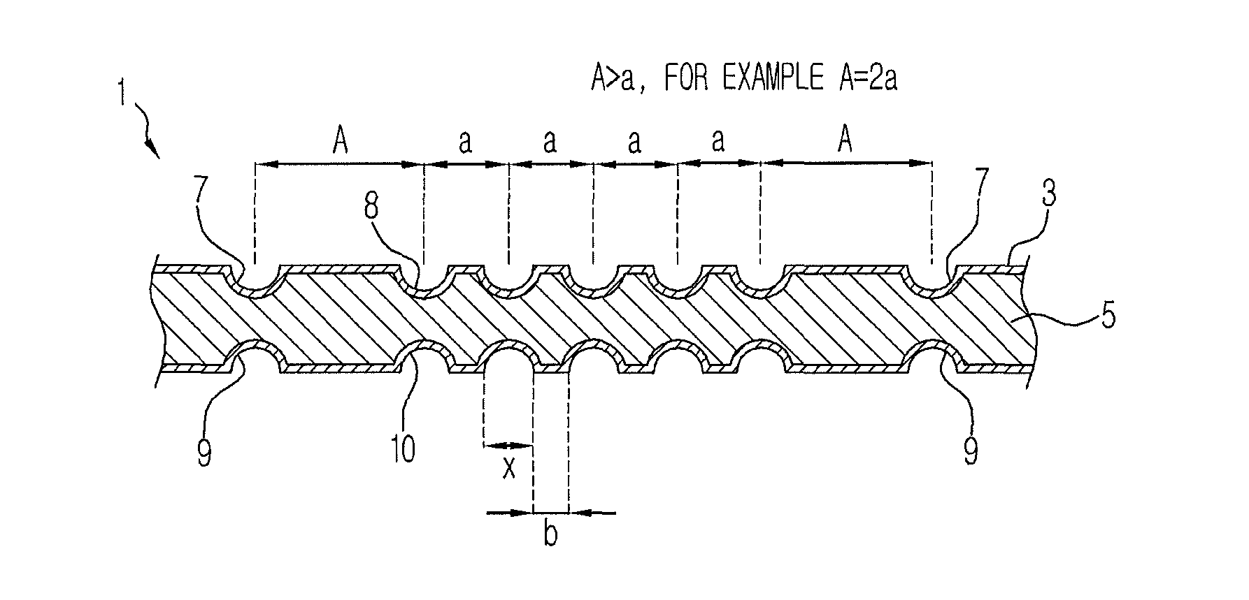
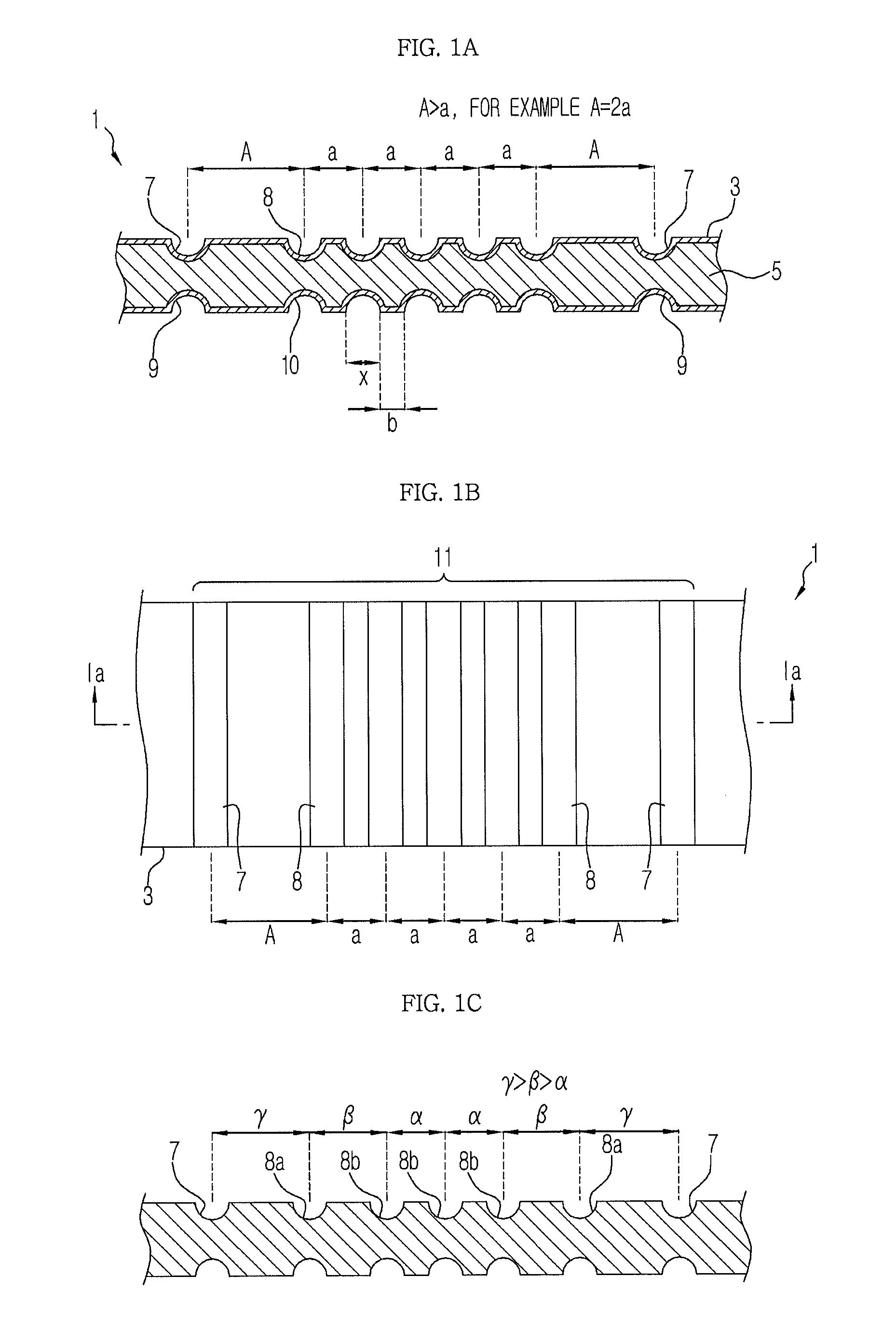
[0093]A vacuum insulation material 1 having a width of 400 mm and a length of 700 mm is manufactured based on construction of the material described in the first concrete example and the manufacturing method described in the second concrete example. The vacuum insulation material 1 has a thickness of about 6 mm and an interval between grooves is as shown in FIG. 6. That is, a plurality of grooves has a groove width of 2 mm and a groove depth of 0.5 mm (±0.2 mm). A bendable region 11 of the vacuum insulation material 1 obtained as described above is folded and bent along the grooves such that the bendable region 11 has an R shape (see FIG. 7A). As a result, the bendable region 11 may be processed to have an R50 shape (i.e. a bending radius of 50 mm). The vacuum insulation material 1 is maintained in this state for three days or more. However, leakage does not occur at the vacuum insulation material 1. In addition, thermal conductivity is measured using a heat flow meter (JIS A 1412-2...

fourth concrete example

[0094]A vacuum insulation material 1 according to this concrete example is obtained by changing the interval between the grooves of the vacuum insulation material 1 according to the third concrete example. Specifically, the interval between the inner grooves 8 and 10 is set to 7.5 mm and the interval between the outer grooves 7 and 9 and the inner grooves 8 and 10 adjacent to the outer grooves 7 and 9 (i.e. the interval between the grooves at the bending start point and the bending end point) is set to 15 mm. As a result, the vacuum insulation material is processed to have an R40 shape (i.e., a bending radius of 40 mm). The vacuum insulation material 1 is maintained in this state for three days or more. However, leakage does not occur at the vacuum insulation material 1.

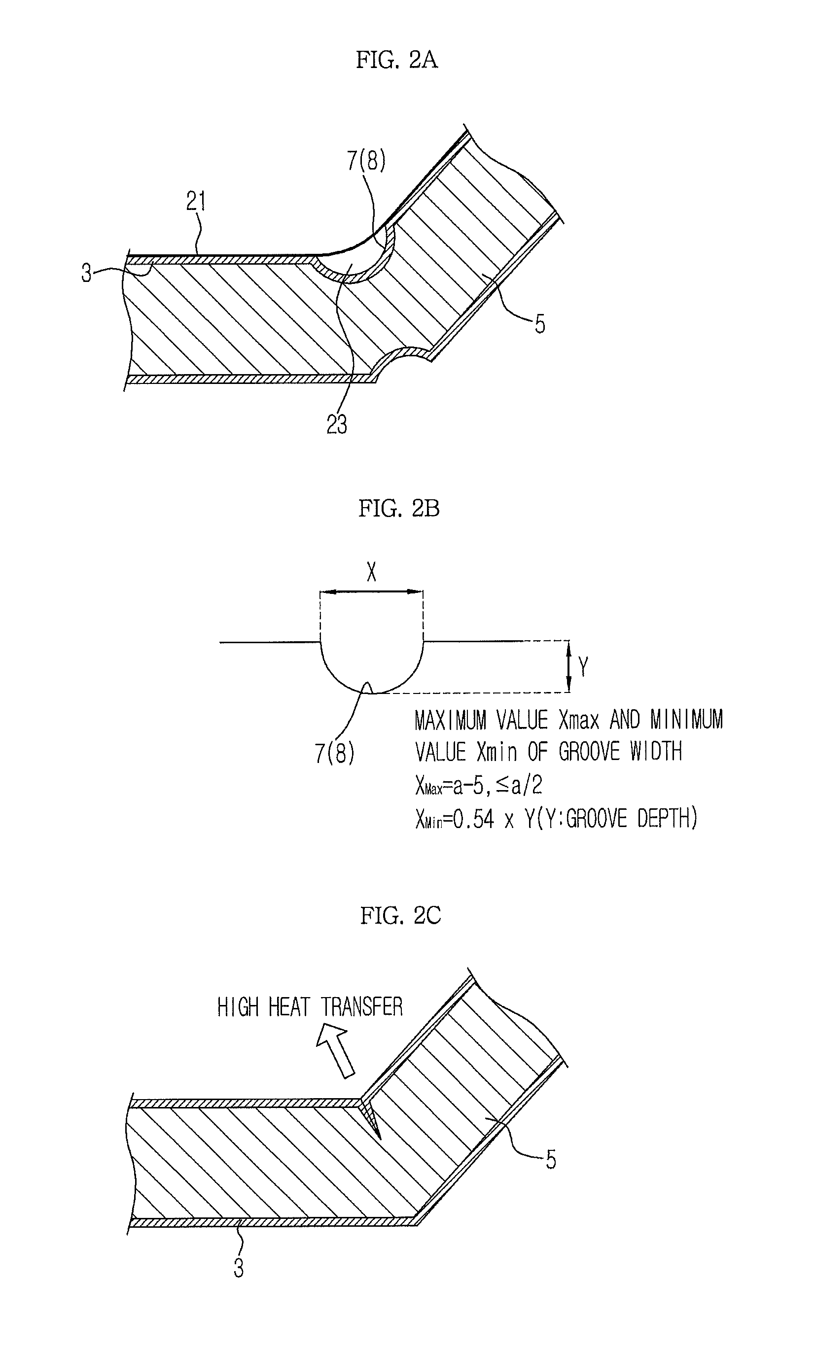
[0095]When the vacuum insulation material 1 is bent, therefore, shape adaptation of the bendable region 11 may be improved. Consequently, the vacuum insulation material 1 may be formed in a desired shape without leak...


PUM


Abstract

A vacuum insulation material having bending formability while restraining reduction in a gas barrier property of a sheathing material. The vacuum insulation material includes a pouch-shaped sheathing material having a gas barrier property and a core received in the sheathing material as a spacer, the vacuum insulation material having a bendable region, a first surface, and a second surface opposite to the first surface, wherein at least one of the first and second surfaces in the bendable region is provided with a plurality of grooves extending at intervals, the grooves include a pair of outer grooves formed in the bendable region and a plurality of inner grooves formed inside the outer grooves, and an interval between each outer groove and a corresponding one of the inner grooves adjacent to each outer groove is greater than an interval between the inner grooves.

Description

CROSS-REFERENCE TO RELATED APPLICATIONS[0001]This application claims the benefit of Japanese Patent Application No. 2013-0021688, filed on Feb. 6, 2013 in the Japanese Patent Office and Korean Patent Application No. 10-2014-0008174, filed on Jan. 23, 2014 in Korean Intellectual Property Office, the disclosures of which are incorporated herein by reference.BACKGROUND[0002]1. Field[0003]Embodiments of the present disclosure relate to a vacuum insulation material and an insulation case unit and a refrigerator using the same.[0004]2. Description of the Related Art[0005]Recently, energy saving devices are in high demand for protection of the environment and conservation of resources. In particular, an apparatus for warming and cooling, such as a refrigerator, a rice cooker, or a hot water supplier, requires an insulation material exhibiting excellent insulation performance to efficiently use heat and to reduce energy consumption.[0006]A vacuum insulation material is well known as an insu...

Claims


Application Information

Patent Timeline
Patent Type & Authority Patents(United States)
IPC IPC(8): F16L59/065F25D23/06
CPCF16L59/065F25D23/062F25D2201/14F25D2500/02Y10T428/231
Inventor TOSHIMITSU, TSURUGATAKEUCHI, KENJIMOTEGI, MANABU
Owner SAMSUNG ELECTRONICS CO LTD
Why Eureka
Try Eureka