Method and apparatus for controlling the engagement of an input gear with an output gear

a technology of input gear and output gear, which is applied in the direction of control devices, belts/chains/gearrings, gear elements, etc., can solve the problems of increased complexity and cost of the transfer case, additional maintenance, etc., and achieve the effect of reducing the output speed of the transmission, increasing torque, and increasing torque supplied

Active Publication Date: 2016-10-18
JAGUAR LAND ROVER LTD
View PDF17 Cites 0 Cited by
  • Summary
  • Abstract
  • Description
  • Claims
  • Application Information

AI Technical Summary

Benefits of technology

[0013]By modifying the input speed of the input shaft such that the rotational speeds of the input gear and the output gear are brought at least substantially into alignment, it is not necessary to provide a synchromesh to mechanically match the speeds of the input and output gears. A tooth on tooth engagement (whereby the teeth of the input and output gears are aligned and the gears are prevented from engaging) could occur if the speeds of the input and output gears were the same at the time of engagement. Accordingly, the step of modifying the calculated target input speed introduces an offset between the rotational speeds of the input and output gears which can, advantageously, help to avoid a tooth on tooth contact. Thus, the rotational speed of the input gear is close enough to that of the output gear to be engaged without the need for a synchromesh, but offset sufficiently (e.g. by 50 rpm) so as to reduce the likelihood of a tooth on tooth engagement.
[0016]The step of modifying an input speed of the input shaft in dependence on the modified target input speed (step (iii)) can be performed when the input shaft is de-coupled from the output shaft. For example, the input speed can be altered after a first input gear has been disengaged and before a second input gear is engaged. With the input and output shafts de-coupled, changes to the input speed can be performed without affecting the output speed.
[0019]The step of modifying the input speed of the input shaft in dependence on the modified target input speed can comprise reducing the input speed. The input speed may have to be reduced if the method is implemented to change from a first input gear to a lower second input gear. A braking torque may be applied to the input shaft to reduce its speed. In arrangements in which the input shaft is coupled to a transmission, this reduction in the input speed can be achieved by changing the transmission to a lower gear and / or relying on internal braking forces within the transmission. The transmission is typically in neutral during the range change so the engine speed is at idle. The selected transmission ratio and drag torque can increase the output shaft speed of the transmission. Selection of additional gears (for example, two or more gears) in the transmission will increase the transmission drag torque, but torque converter slip can prevent the engine stalling.
[0020]The step of modifying the input speed of the input shaft in dependence on the modified target input speed can comprise increasing the input speed. The input speed may have to be increased if the method is implemented to change from a first input gear to a higher second input gear. In arrangements in which the input shaft is coupled to a transmission, a higher gear in the transmission may be engaged to increase the output speed of the transmission; and / or an increase in torque may be supplied to the transmission to increase the input speed of the input shaft. The transmission control module can request an increase in the engine torque which results in an increase in the output speed of the engine. The input speed of the transmission is thereby increased resulting in an increase in the output speed of the transmission (and the input shaft coupled to the input gear).
[0035]The speed controller can be operable to control the transmission to reduce the input speed of the input shaft. The speed controller may cause a braking torque to be applied to the transmission. The braking torque can be a result of internal friction / drag within the transmission. Alternatively, or in addition, the speed controller can initiate a change to a lower gear in the transmission to reduce the output speed of the transmission.
[0036]The speed controller can be operable to control the transmission to increase the input speed of the input shaft. The speed controller can initiate a change to a higher gear in the transmission to increase the input speed of the input shaft. Alternatively, or in addition, the speed controller can request an increase in torque from an engine or motor connected to the transmission. The resulting increase in the output speed of the engine will increase the input speed of the transmission and, therefore, the output speed of the transmission to which the input shaft is connected. The control signal could, for example, be supplied to a transmission control module to initiate the gear change and / or an engine control module to increase torque supplied to the transmission.

Problems solved by technology

Providing a synchromesh increases the complexity and cost of the transfer case.
Moreover, wear on the components in the transfer case can result in additional maintenance being required.

Method used


Image

  • Method and apparatus for controlling the engagement of an input gear with an output gear
  • Method and apparatus for controlling the engagement of an input gear with an output gear

Examples


Embodiment Construction

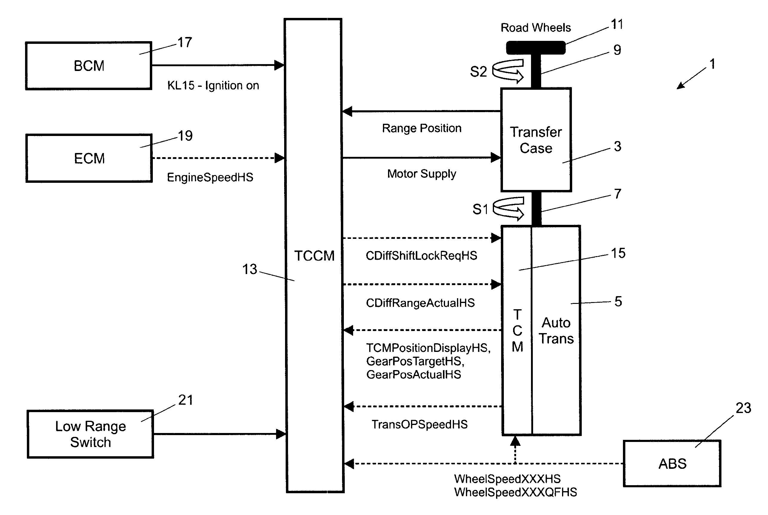
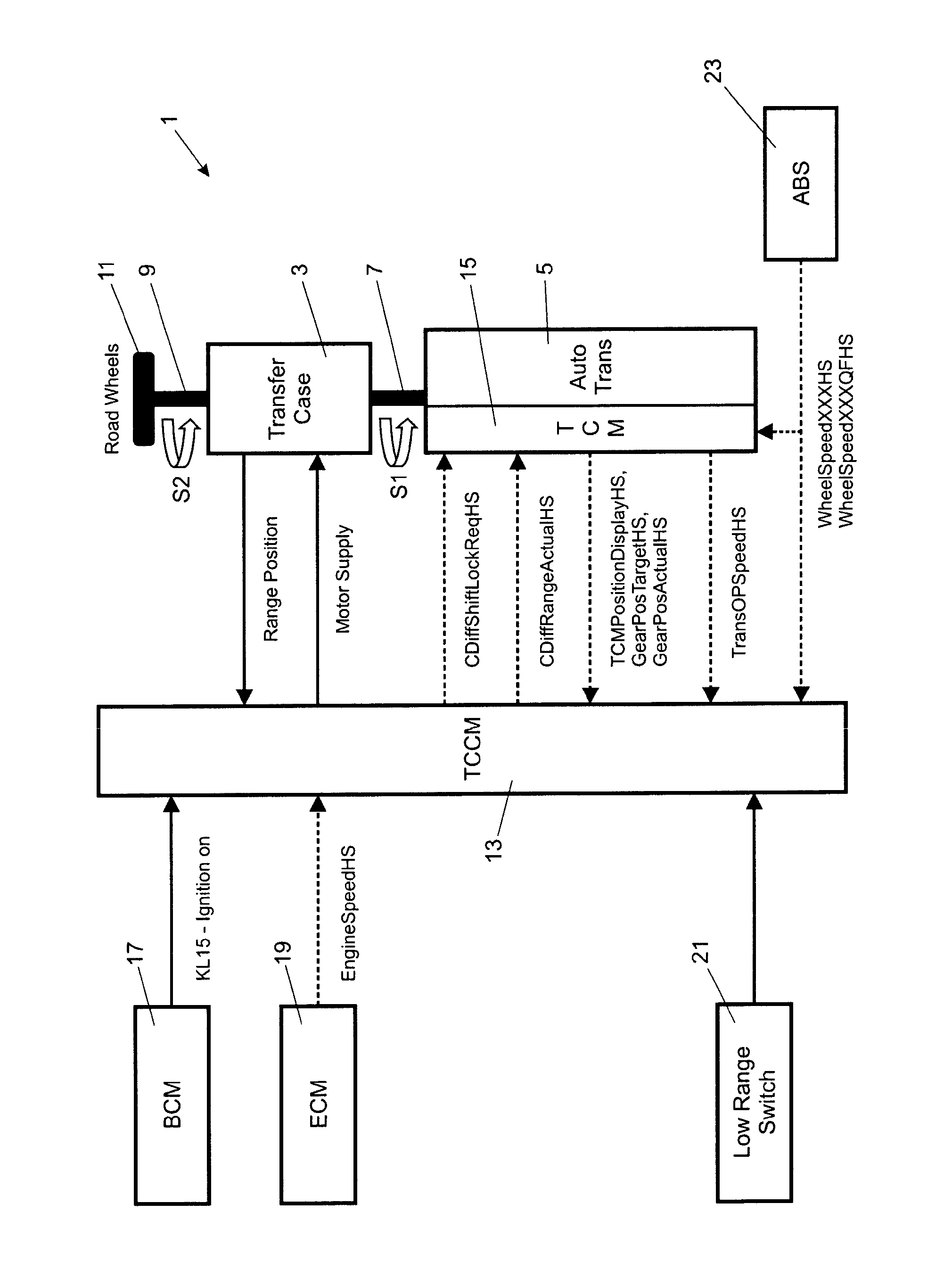
[0048]A transfer case control system 1 for a motor vehicle will now be described with reference to FIG. 1. The transfer case control system 1 controls a transfer case 3 (also referred to as a transfer box) and an automatic transmission 5. The transfer case 3 comprises a high input gear train and a low input gear train for respective high and low ranges. The transfer case control system 1 in accordance with the present invention allows on the move changes between the high and low ranges without the need for synchromesh gears in the transfer case 3.

[0049]The transfer case 3 is driven by a transfer case input shaft 7 connected to the output shaft of the transmission 5. The transfer case 3 has a transfer case output shaft 9 which drives a set of road wheels 11. The transfer case input shaft 7 rotates at a first speed S1 and the transfer case output shaft 9 rotates at a second speed S2. When operating in the low range the transfer case 3 provides a gear ratio of 3:1 to give the vehicle a...


PUM


Abstract

The present invention relates to a method of engaging an input gear with an output gear in a drivetrain (3). The input gear is coupled to an input shaft (7) and the output gear is coupled to an output shaft (9). The method includes calculating a target input speed (S1′) for the input shaft (7) to match a rotational speed of the input gear to a rotational speed of the output gear. The calculated target input speed (S1′) is then modified to include an offset and the input speed (S1) of the input shaft (7) is then modified in dependence on the modified target input speed (S1″). The input gear and the output gear engage when the input speed (S1) of the input shaft (7) at least substantially matches the modified target input speed (S1″). The present invention also relates to an apparatus.

Description

TECHNICAL FIELD[0001]The present invention relates to a method and apparatus for controlling the engagement of an input gear and an output gear. The input gear and the output gear can form part of a transfer case for a motor vehicle. Aspects of the invention relate to a method, to an apparatus, to a transmission system and to a vehicle.BACKGROUND OF THE INVENTION[0002]A transfer case having a low gear range and a high gear range is commonly provided in a four wheel drive vehicle. The torque input from the transmission is passed to a transfer box input shaft. A differential, such as a Torsen® differential, can be provided in the transfer case to split torque between the front and rear wheels of the vehicle. The high range is used for normal road driving and also for off-road driving across dry, level terrain. The low range may be engaged for low speed maneuvering, such as reversing a trailer, negotiating steep slippery surfaces or boulder strewn terrain. The low range can also be use...

Claims


Application Information

Patent Timeline
Patent Type & Authority Patents(United States)
IPC IPC(8): F16H61/04F16H61/02B60K17/346
CPCF16H61/0202F16H61/0403B60K17/3467F16H2061/047B60W10/101B60W30/19
Inventor VINCENT, DARRENSUTTON, SIMONJERGER, ROB
Owner JAGUAR LAND ROVER LTD
Why Eureka
Try Eureka