
Devices and methods for reducing cardiac valve regurgitation

a technology of cardiac valve and valve valve, which is applied in the field of devices and methods for reducing cardiac valve regurgitation, can solve the problems of heart valves that may lose their ability to close properly, leak backwards, and serious impairment of heart function, so as to avoid blood stagnation and reduce regurgitation

Active Publication Date: 2016-10-25
EDWARDS LIFESCIENCES CORP
View PDF33 Cites 115 Cited by
  • Summary
  • Abstract
  • Description
  • Claims
  • Application Information

AI Technical Summary

Benefits of technology

The patent describes a system for reducing heart valve regurgitation. It consists of a flexible rail that is anchored in the heart, a delivery catheter with a coaptation member, and a locking collet to secure the catheter and coaptation member in place. The system reduces regurgitation by helping to close the valve and preventing blood from leaking back into the heart.

Problems solved by technology

The function of the heart may be seriously impaired if any of the heart valves are not functioning properly.
The heart valves may lose their ability to close properly due to e.g. dilation of an annulus around the valve, ventricular dilation, or a leaflet being flaccid causing a prolapsing leaflet.
The inability of the heart valve to close properly can cause a leak backwards (i.e., from the outflow to the inflow side), commonly referred to as regurgitation, through the valve.
Heart valve regurgitation may seriously impair the function of the heart since more blood will have to be pumped through the regurgitating valve to maintain adequate circulation.
Heart valve regurgitation decreases the efficiency of the heart, reduces blood circulation, and adds stress to the heart.
In early stages, heart valve regurgitation leaves a person fatigued or short of breath.
If left unchecked, the problem can lead to congestive heart failure, arrhythmias or death.
However, open-heart surgery is highly invasive and is therefore not an option for many patients.

Method used


Image

  • Devices and methods for reducing cardiac valve regurgitation
  • Devices and methods for reducing cardiac valve regurgitation
  • Devices and methods for reducing cardiac valve regurgitation

Examples


Embodiment Construction

[0060]The following description refers to the accompanying drawings, which illustrate specific embodiments of the invention. Other embodiments having different structures and operation do not depart from the scope of the present invention.

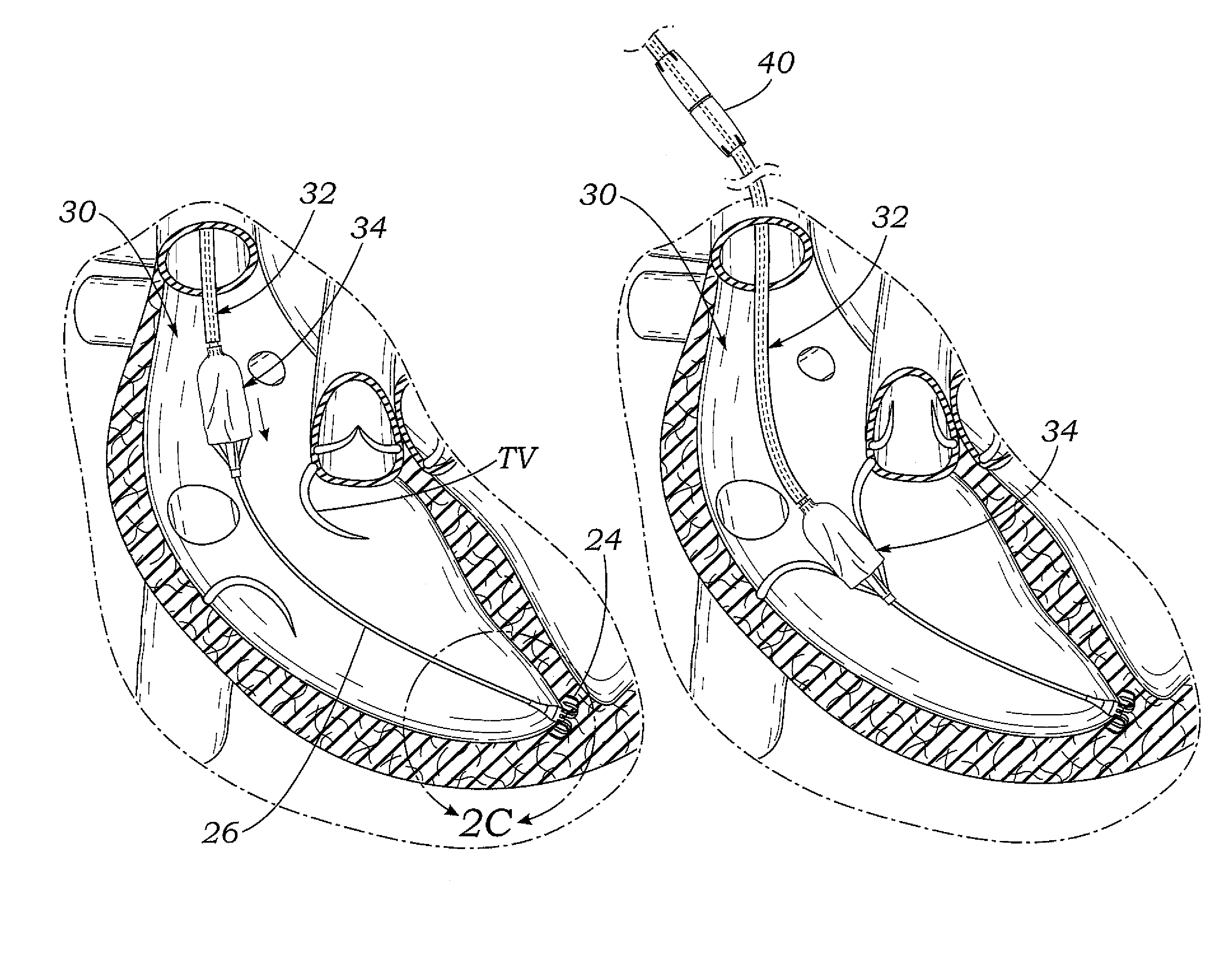
[0061]Exemplary embodiments of the present disclosure are directed to devices and methods for improving the function of a defective heart valve. It should be noted that various embodiments of coapting elements and systems for delivery and implant are disclosed herein, and any combination of these options may be made unless specifically excluded. For example, any of the coapting elements disclosed may be combined with any of the flexible rail anchors, even if not explicitly described. Likewise, the different constructions of coapting elements may be mixed and matched, such as combining any tissue cover with any inner flexible support, even if not explicitly disclosed. In short, individual components of the disclosed systems may be combined unless mu...


PUM


Abstract

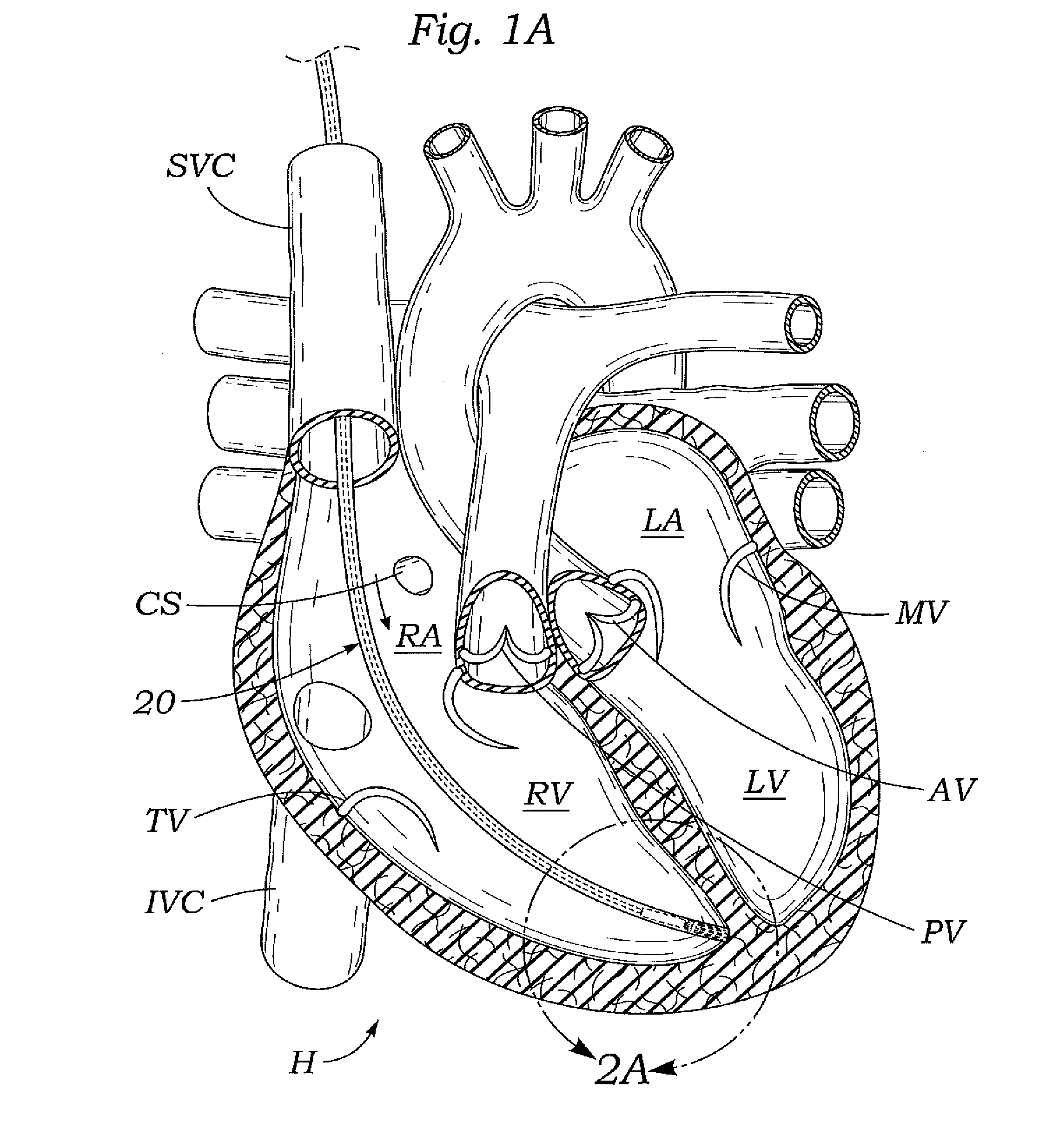
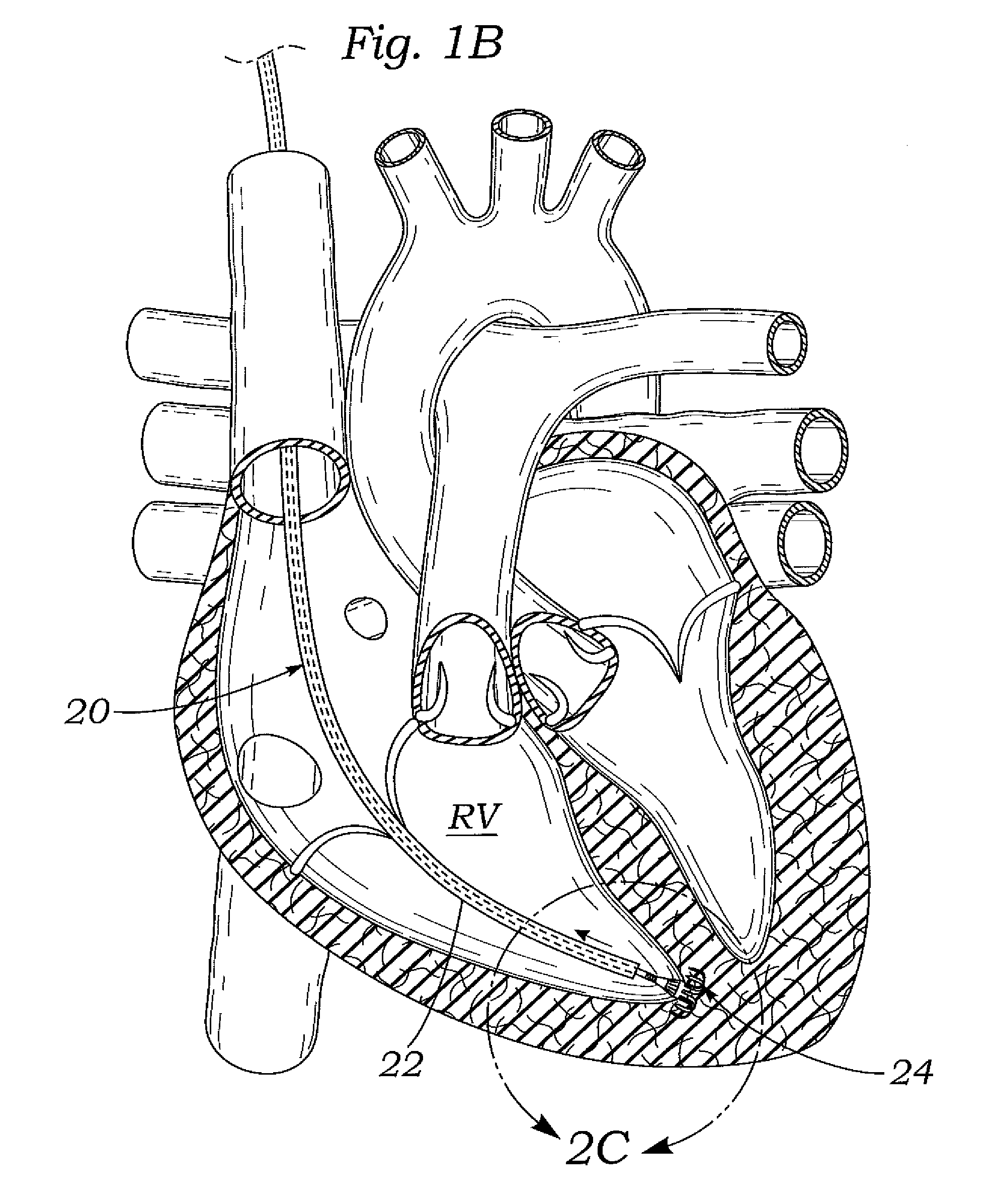
The present invention relates to devices and methods for improving the function of a defective heart valve, and particularly for reducing regurgitation through an atrioventricular heart valve—i.e., the mitral valve and the tricuspid valve. For a tricuspid repair, the device includes an anchor deployed in the tissue of the right ventricle, in an orifice opening to the right atrium, or anchored to the tricuspid valve. A flexible anchor rail connects to the anchor and a coaptation element on a catheter rides over the anchor rail. The catheter attaches to the proximal end of the coaptation element, and a locking mechanism fixes the position of the coaptation element relative to the anchor rail. Finally, there is a proximal anchoring feature to fix the proximal end of the coaptation catheter subcutaneously adjacent the subclavian vein. The coaptation element includes an inert covering and helps reduce regurgitation through contact with the valve leaflets.

Description

RELATED APPLICATIONS[0001]The present application claims priority under 35 U.S.C. §119 to U.S. Provisional Application Ser. No. 61 / 647,973, filed May 16, 2012, and to U.S. Provisional Application Ser. No. 61 / 734,728, filed Dec. 7, 2012, the disclosures of which are expressly incorporated herein by reference.FIELD OF THE INVENTION[0002]The present invention relates generally to devices and methods for improving the function of a defective heart valve. The devices and methods disclosed herein are particularly well adapted for implantation in a patient's heart for reducing regurgitation through a heart valve.BACKGROUND OF THE INVENTION[0003]The function of the heart may be seriously impaired if any of the heart valves are not functioning properly. The heart valves may lose their ability to close properly due to e.g. dilation of an annulus around the valve, ventricular dilation, or a leaflet being flaccid causing a prolapsing leaflet. The leaflets may also have shrunk due to disease, e....

Claims


Application Information

Patent Timeline
Patent Type & Authority Patents(United States)
IPC IPC(8): A61F2/24
CPCA61F2/2427A61F2/246A61F2/2454A61F2/2463A61F2/2466A61F2/2424A61F2210/0061A61F2230/0023A61F2250/001A61F2250/0003A61F2210/0014A61B17/064A61B2017/0649A61B2017/0641A61B17/068A61F2/2433
Inventor ROWE, STANTON J.SCHWARTZ, ROBERTVAN TASSEL, ROBERTKHALIL, VIVIANSPINNER, ERINZIMMERMAN, NEILSIEGEL, ALEXANDER J.
Owner EDWARDS LIFESCIENCES CORP
Learn More