Tubular linear motor with magnetostrictive sensor

a technology of magnetostrictive sensor and linear motor, which is applied in the direction of converting sensor output, dynamo-electric machines, instruments, etc., can solve the problems of high magnetic field, noise, and difficult application of magnetostrictive sensors in motors, and achieve the effect of improving the accuracy of position measuremen

Inactive Publication Date: 2016-10-25
MTS SENSOR TECH
View PDF25 Cites 6 Cited by
  • Summary
  • Abstract
  • Description
  • Claims
  • Application Information

AI Technical Summary

Benefits of technology

[0006]In the embodiments described below, a high permability end flux diverter is provided adjacent a second stack end of magnet stack. The end flux diverter prevents the second stack end from magnetizing a magnetostrictive element. In a further embodiment, an auxiliary flux diverter in the form of a ferromagnetic pusher rod is also provided.
[0026]In each of the first, second and third alternative aspects, the use of a stack end flux diverter and a position indicating magnet can be avoided, reducing cost and complexity of construction around the first stack end.
[0028]In each of the first, second and third alternative aspects, the measurement of position can be made more accurate with the use of a shield tube that provides noise immunity against the magnetic fields of the motor coil during operation.
[0029]In each of the first, second and third alternative aspects, the diversion of magnetic flux by an end flux diverter and a pusher rod helps to avoid interference with the magnetostrictive element.
[0030]In each of the first, second and third alternative aspects, a shield tube can alternatively be attached to a first stator end, thereby avoiding adding a moving mass of the shield tube to the slider.

Problems solved by technology

A measurement environment with high magnetic fields is problematic for magnetostrictive sensors.
The high magnetic fields tend to introduce noise into the measurement of position using magnetostrictive sensors.
High magnetic fields are present in motors, especially under high load conditions, and applications of magnetostrictive sensors in motors is difficult.

Method used


Image

  • Tubular linear motor with magnetostrictive sensor
  • Tubular linear motor with magnetostrictive sensor
  • Tubular linear motor with magnetostrictive sensor

Examples


Embodiment Construction

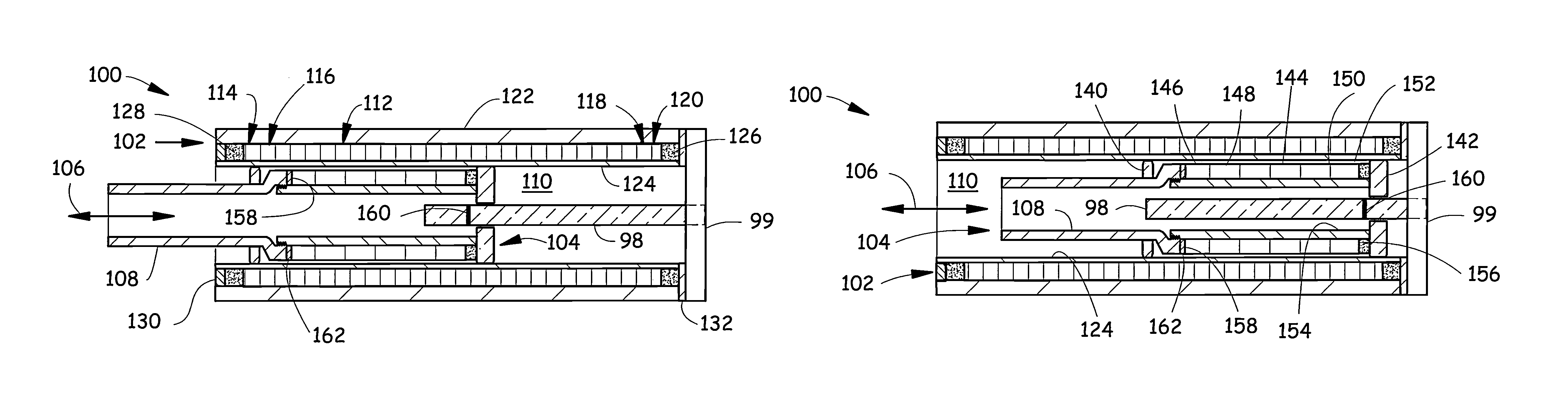
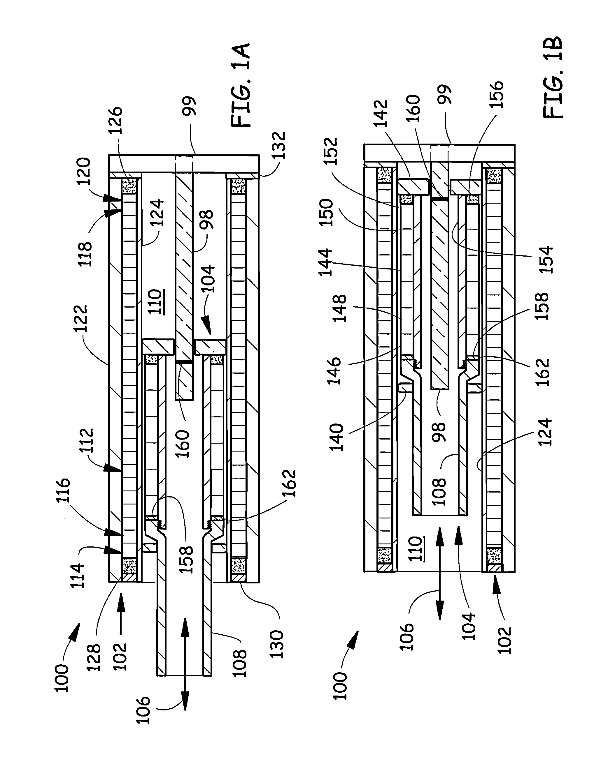
[0042]FIGS. 1A, 1B illustrate an exemplary embodiment of a tubular linear motor 100 with a magnetostrictive sensor element 98. The motor 100 comprises a stator 102 that is a portion of the motor 100 that is typically mounted to a non-moving portion of a machine (not illustrated). The motor 100 comprises a slider 104 that is a portion of the motor 100 that moves in a sliding fashion relative to the stator 102. The slider 104 slides, for example, along an axis 106 between a first (more extended) position illustrated in FIG. 1A and a second (less extended) position illustrated in FIG. 1B. The slider 104 includes a pusher rod 108 that is typically attached to a machine part (not illustrated) which is intended to be moved by the motor 100 relative to the non-moving portion of the machine. The position-sensing magnetostrictive element 98 is mounted at a first stator end 99 of the stator 102 and extends along a stator bore 110. The magnetostrictive element 98 is connectable to circuitry (s...


PUM


Abstract

A motor includes a position-sensing magnetostrictive element that extends along a stator bore. A slider slides in the stator bore and includes a stack of motor magnets. The stack includes a first stack end that provides a magnetic field pattern that magnetizes a region of the magnetostrictive element. The motor includes shield elements such as a non-magnetic shield tube and a magnetic flux diverter.

Description

BACKGROUND OF THE INVENTION[0001]The discussion below is merely provided for general background information and is not intended to be used as an aid in determining the scope of the claimed subject matter.[0002]A measurement environment with high magnetic fields is problematic for magnetostrictive sensors. The high magnetic fields tend to introduce noise into the measurement of position using magnetostrictive sensors. High magnetic fields are present in motors, especially under high load conditions, and applications of magnetostrictive sensors in motors is difficult.SUMMARY[0003]This summary and the Abstract herein are provided to introduce a selection of concepts in a simplified form that are further described below in the Detailed Description. This Summary and the Abstract are not intended to identify key features or essential features of the claimed subject matter, nor are they intended to be used as an aid in determining the scope of the claimed subject matter. The claimed subjec...

Claims


Application Information

Patent Timeline
Patent Type & Authority Patents(United States)
IPC IPC(8): H02K41/02H02K41/03G01D5/48H02K11/00H02K1/27H02K1/28H02K11/02
CPCH02K11/026G01D5/485H02K41/031H02K1/2733H02K1/28H02K11/022H02K11/21H02K11/215H02K11/012
Inventor BESTE, ANDRESAPP, MANFREDWALTER, INGO
Owner MTS SENSOR TECH
Why Eureka
Try Eureka