Separation membrane for membrane distillation

a separation membrane and membrane technology, applied in the direction of membranes, separation processes, filtration separation, etc., can solve the problems of large energy consumption, reverse osmosis process, evaporation process and reverse osmosis process, etc., and achieve the effect of increasing the yield of treated water

Inactive Publication Date: 2016-11-01
KOREA INST OF SCI & TECH
View PDF12 Cites 2 Cited by
  • Summary
  • Abstract
  • Description
  • Claims
  • Application Information

AI Technical Summary

Benefits of technology

[0014]Therefore, the present invention has been made keeping in mind the above problems encountered in the related art, and an object of the present invention is to provide a membrane distillation system on a unit scale, wherein from feed water that is fed to the feed water side of the membrane distillation system, the amount of vapor that reaches the treated water side through the separation membrane due to a vapor pressure difference may be increased to thereby improve water treatment efficiency.
[0020]According to the present invention, a separation membrane for membrane distillation is provided in bent form, so that the cross-sectional area of the separation membrane through which a separating material in a vapor phase can pass from a feed water side to a treated water side is large compared to conventional planar separation membranes, thereby increasing the yield of treated water in a membrane distillation system on a unit scale.

Problems solved by technology

An evaporation process and a reverse osmosis process, both currently useful for production of pure water or for desalination, require a large quantity of energy.
In particular, a reverse osmosis process is problematic because a plurality of pretreatment steps has to be implemented before use attributed to pollution and fouling, making it difficult to control the operation of the process.
Moreover, since this process operates at high pressure, a large quantity of electric energy is used as a pump power source, undesirably incurring high management cost.
When the membrane distillation process having the advantages described above is employed in a desalination (desalting) process, low utility cost and high durability of separation systems may result.
However, the membrane distillation process is disadvantageous because the separating material may pass through the separation membrane only when it is in a vapor phase, due to a vapor pressure difference between the feed water side and the treated water side, undesirably incurring low productivity compared to other water treatment processes.

Method used


Image

  • Separation membrane for membrane distillation
  • Separation membrane for membrane distillation

Examples


Embodiment Construction

[0024]Hereinafter, a detailed description will be given of the present invention.

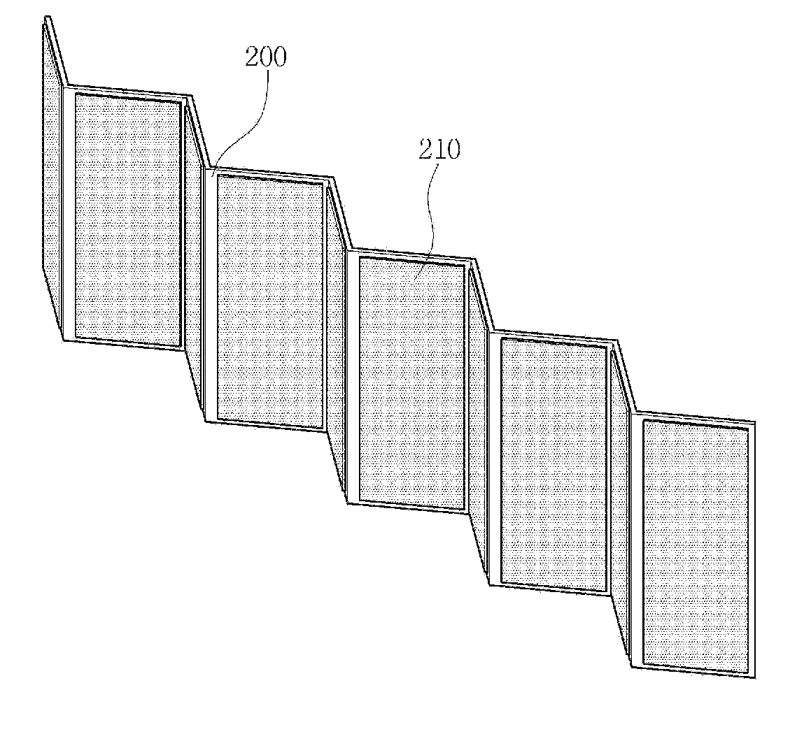
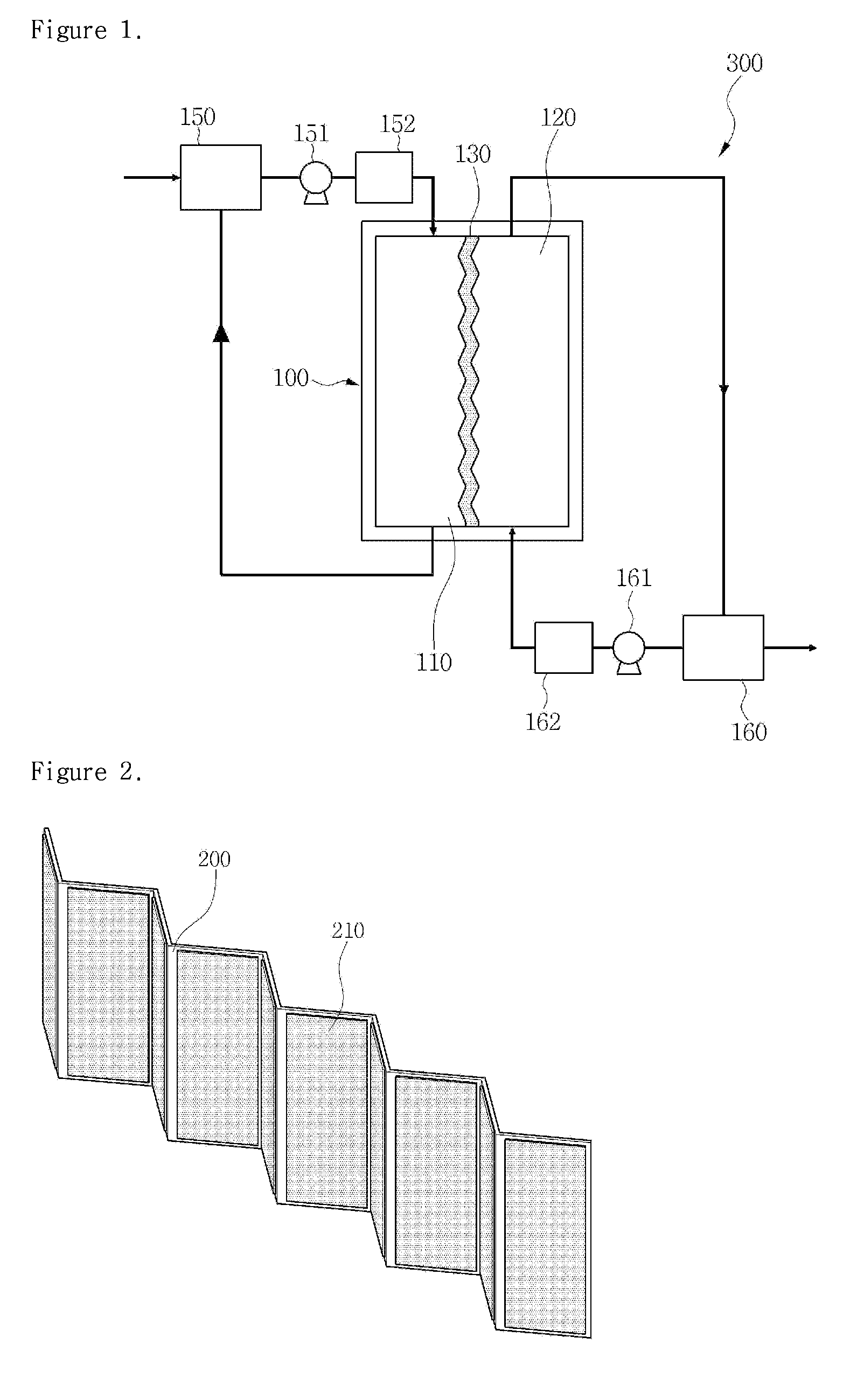
[0025]The present invention pertains to a separation membrane for membrane distillation. More specifically, the present invention pertains to a separation membrane for membrane distillation including a feed water side for feeding raw water and a treated water side for discharging treated water, wherein the separation membrane is provided in bent form by a support frame.

[0026]In the present invention, the separation membrane is preferably a hydrophobic polymer separation membrane. The reason why the hydrophobic polymer separation membrane is used is as follows: a solvent or solute (a hydrophilic material) in a liquid phase, having a surface tension greater than that of the separation membrane, does not pass through membrane pores but is repelled from the surface of the separation membrane, and thus, the separating material is converted into a vapor phase at the entrances of the surface pores of the separ...


PUM

PropertyMeasurementUnit
surface pore sizeaaaaaaaaaa
thicknessaaaaaaaaaa
pore sizeaaaaaaaaaa

Abstract

Disclosed is a separation membrane for membrane distillation, including a feed water side for feeding raw water and a treated water side for discharging treated water, wherein the separation membrane is provided in bent form by a support frame.

Description

CROSS-REFERENCE TO RELATED APPLICATIONS[0001]This application claims the benefit of Korean Application No. 10-2014-0012758, filed on Feb. 4, 2014 in the Korean Intellectual Property Office, the entire disclosure of which is incorporated herein by reference for all purposes.BACKGROUND OF THE INVENTION[0002]1. Field of the Invention[0003]The present invention relates to a separation membrane for water treatment, the membrane being used in a water treatment process, especially a membrane distillation process.[0004]2. Description of the Related Art[0005]A membrane distillation process is performed in such a manner that phase changes occur on the surface of a hydrophobic polymer separation membrane and the resulting vapor passes through the surface micropores of the separation membrane and is thus condensed and separated. This process is applied to a desalting process for separating and removing a non-volatile material or a material having relatively low volatility, or to separation of a...

Claims


Application Information

Patent Timeline
Patent Type & Authority Patents(United States)
IPC IPC(8): B01D39/00B01D63/00B01D27/06B01D27/07B01D61/36B01D63/14B01D69/06C02F1/44
CPCB01D61/366B01D63/14B01D69/06B01D61/364B01D2313/025B01D63/08B01D71/06C02F1/447B01D71/36B01D71/34B01D71/68B01D71/643B01D71/64B01D71/261B01D71/262B01D71/56B01D2325/38B01D2325/02834B01D2325/04
Inventor JEONG, SEONGPILLEE, SEOCKHEON
Owner KOREA INST OF SCI & TECH
Why Eureka
Try Eureka