Sealing arrangement for a rotating shaft

Active Publication Date: 2016-11-01
SULZER MANAGEMENT AG
View PDF7 Cites 0 Cited by
  • Summary
  • Abstract
  • Description
  • Claims
  • Application Information

AI Technical Summary

Benefits of technology

[0027]The sealing system is usually arranged at a pump so that the insulation chamber is arranged adjacent to a region of the pump from which the conveyed fluid can move into the insulation chamber. It is then the object of the sealing system to prevent an exit of the fluid moved into the insulation chamber into the environment. If the pump is used for conveying liquefied natural gas, liquefied natural gas can move into the insulation chamber in which it at least partly evaporates due to the higher temperatures in the insulation chamber. The gaseous sealing fluid which thus arises can move past the insulation element into the sealing chamber and can build up the sealing fluid pressure there. To lead off the fluid to be conveyed which does not evaporate in the insulation chamber and thus remains liquid, a lead-off line is in particular provided for the liquid fluid. The lead-off line in particular leads to the intake side of the pump. It is also prevented by the leading off of the liquid fluid that it can move past the insulation element into the sealing chamber. The lead-off line can in particular also serve as a pressure connection via which the pressure in t

Problems solved by technology

Liquefied natural gas has a temperature of approximately −160°

Method used


Image

  • Sealing arrangement for a rotating shaft
  • Sealing arrangement for a rotating shaft

Examples


Embodiment Construction

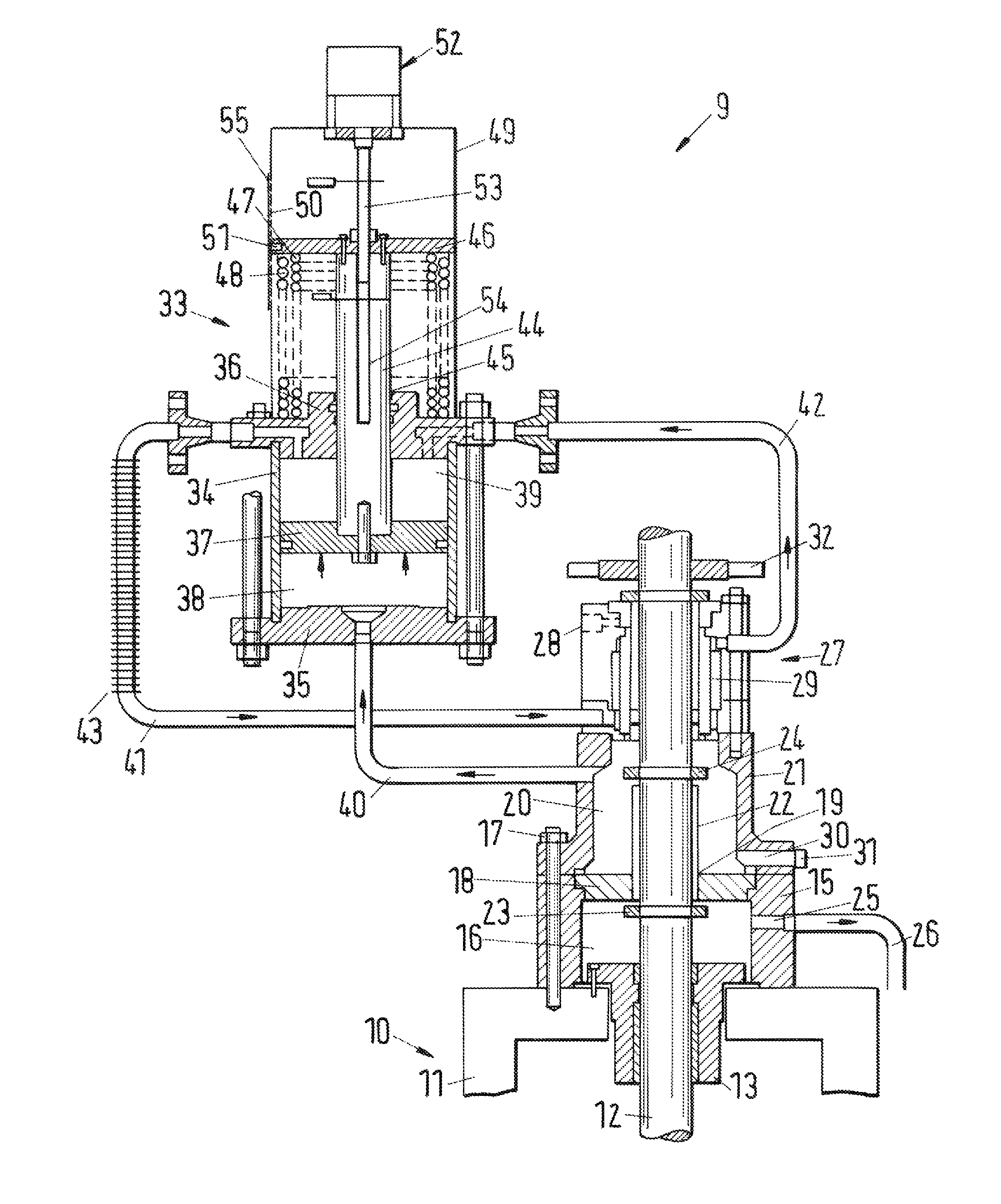
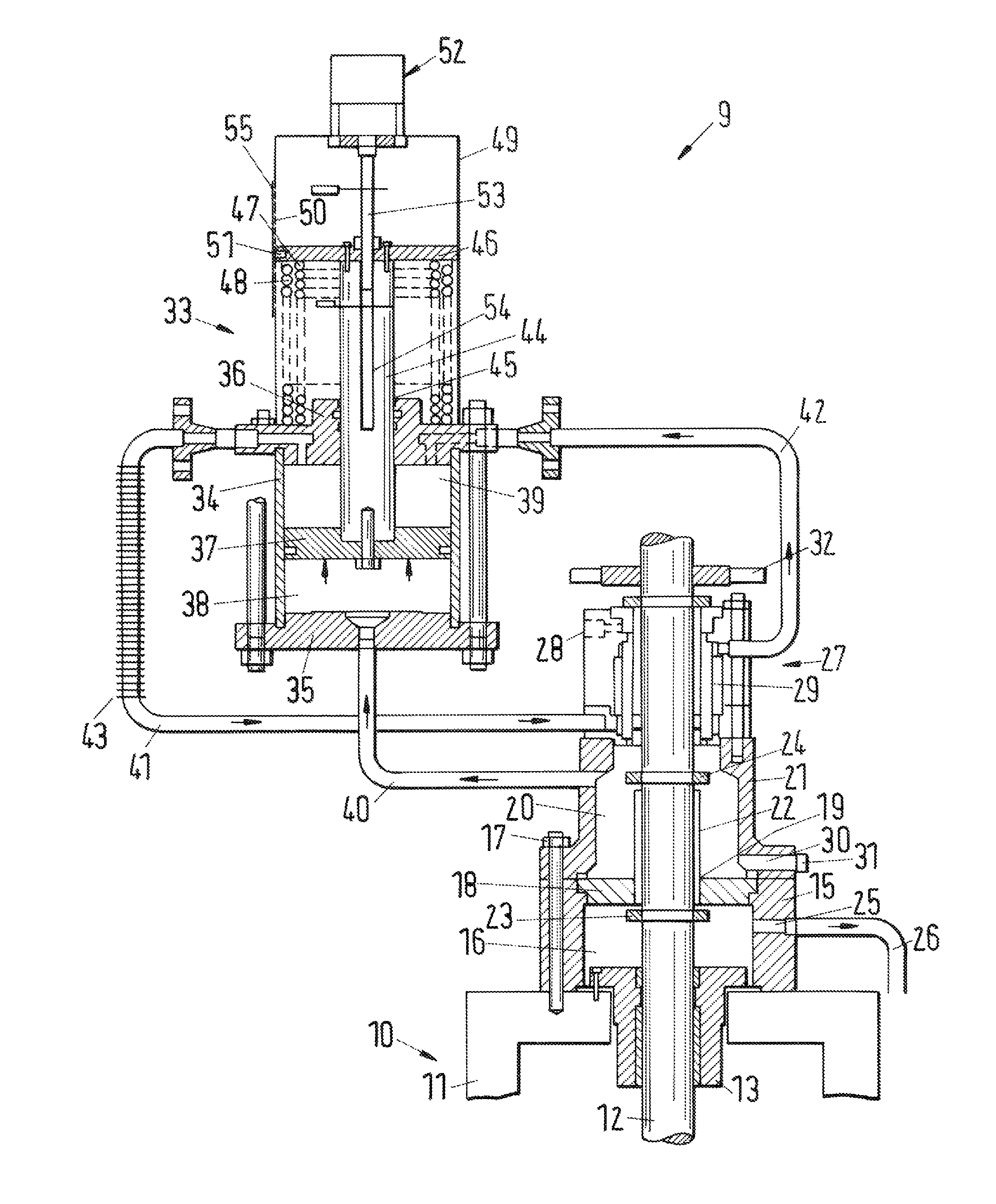
[0034]In accordance with FIG. 1, a pump 10 has a pump housing 11 and a rotatable shaft 12 in the form of a drive shaft or pump shaft. The pump 10 is driven via the shaft 12 by an electric motor, not shown. The pump 10 is arranged vertically and serves for the conveying of liquefied natural gas so that liquefied natural gas can exit at a throttle bushing 13 through which the shaft 12 exits through the pump housing 11. The throttle bushing 13 is sealed with respect to the environment by means of a sealing system 9. Only details of the shaft 12 and of the pump housing 11 are shown; the representation of further components of the pump 10 has likewise been dispensed with.

[0035]A part of the throttle bushing 13 projecting from the pump housing 11 is surrounded by a cylindrical outer wall 15 of an insulation chamber 16. The outer wall 15 of the insulation chamber 16 is screwed to the pump housing 11 using a plurality of screws of which only one screw 17 is shown. The insulation chamber 16 ...


PUM


Abstract

The invention relates to a sealing system, in particular for sealing pump shafts of vertically arranged pumps for conveying liquefied natural gas (LNG) or other cryogenic fluids below −80° C. The sealing system has a mechanical seal arrangement. A barrier fluid flows through the mechanical seal arrangement at a barrier fluid pressure. The mechanical seal arrangement prevents a sealing fluid from exiting a sealing chamber. The barrier fluid pressure is higher than a sealing fluid pressure in the sealing chamber.

Description

BACKGROUND OF THE INVENTION[0001]The invention relates to a sealing system for sealing a rotating shaft projecting through a sealing chamber.[0002]A sealing system of this category has already been offered and sold by Sulzer Pumpen AG for some years under the sales name “J-Unit Cryogenic Sealing System”.[0003]This sealing system is in particular used for sealing pump shafts of vertically arranged pumps for conveying for example liquefied natural gas (LNG). Liquefied natural gas has a temperature of approximately −160° C. so that standard sealing arrangements cannot easily be used. This sealing system is in particular characterized in that the cold liquefied natural gas is separated from the mechanical seal arrangement exerting the sealing function. This is achieved in that no liquefied natural gas is located in a sealing chamber adjoining the mechanical seal arrangement, but rather natural gas which has a much higher temperature than the liquefied natural gas. Standardized and thus ...

Claims


Application Information

Patent Timeline
IPC IPC(8): F01D11/04F01D11/06F16J15/34
CPCF16J15/3404
Inventor ZENTIC, CLINT
Owner SULZER MANAGEMENT AG
Why Eureka
Try Eureka