Object information acquiring apparatus

a technology of object information and acquisition apparatus, applied in the field of object information acquisition apparatus, can solve problems such as displacement measurement using ultrasound waves, and achieve the effect of improving accuracy

Active Publication Date: 2016-11-01
CANON KK
View PDF22 Cites 5 Cited by
  • Summary
  • Abstract
  • Description
  • Claims
  • Application Information

AI Technical Summary

Benefits of technology

[0025]According to the present invention, the accuracy is improved upon adopting the aperture synthesis method in order to measure a displacement in use of ultrasound waves in the object information acquiring apparatus is adopted.
[0026]Further features of the present invention will become apparent from the following description of exemplary embodiments with reference to the attached drawings.

Problems solved by technology

Upon calculating the motion of a tissue or hardness of a tissue portion like this, displacement measured with ultrasound waves is frequently used, and therefore in recent ultrasound diagnostic apparatuses, a critical technical issue is the displacement measurement using ultrasound waves.

Method used


Image

  • Object information acquiring apparatus
  • Object information acquiring apparatus
  • Object information acquiring apparatus

Examples


modification 1

[0120](Modification 1 of Displacement Calculation)

[0121]In the above example, a technique to use IQ signals separated into the hyperbola index axis direction and the ellipse index axis direction was described, but a technique to extract phase information and displacement information from a plurality of waveform signals may be used.

[0122]For example, the displacement can also be calculated using a following technique.

[0123]Envelope curves of the second aperture synthesis signals acquired at different timings are determined, and a general displacement (δu′, δv′) is estimated by the cross-correlation of these envelope curves. After correcting the general displacement, a phase difference (φu′, φv′) is calculated using complex correlation. Further, instantaneous frequencies (fu, fv) at a target position are estimated.

[0124]The displacement δu in the hyper bola index axis direction and the displacement δv in the ellipse index axis direction can be calculated using the following Expression...

modification 2

[0128](Modification 2 of Displacement Calculation)

[0129]The displacement can also be calculated using the following technique.

[0130]The envelope curves of the second aperture synthesis signals acquired at different timings are determined, and a general displacement (δu′, δv′) is estimated by the cross-correlation of these envelope curves. Then an argument R (Δu, Δv: u, v) of a complex correlation is calculated by providing an arbitrary amount of deviation Δu and Δv, assuming that the second aperture synthesis signals, after correcting the general displacement, are s1(u,v) and s2(u,v). This is given by Expression (31).

[0131][Math.⁢17]R⁡(Δ⁢⁢u,Δ⁢⁢v⁢:⁢⁢u,v)=arg⁢{∫∫Ω⁡(x,y)⁢s2⁡(ξ,η)⁢s1*⁡(ξ+Δ⁢⁢u,η+Δ⁢⁢v)⁢ⅆξ⁢ⅆη}(31)

[0132]The argument R (Δu, Δv: u, v) of the complex correlation becomes 0 when the displacement (δu′+Δu, δv′+Δv) coincides with the true displacements. In concrete terms, approximating that the argument changes as a linear function, linear interpolation is performed with a pluralit...

embodiment 1

[0156]Modifications 1 and 2 of the displacement measurement described in Embodiment 1 are preferable examples in terms of controlling the measurement errors in the displacement measurement and improving the signal level as mentioned above. However in these examples, the encoded pulse need not always be used in terms of controlling the measurement error. In other words, the effect of controlling the measurement error can be exhibited even if the transmitting pulse is not an encoded pulse.


PUM

PropertyMeasurementUnit
diameteraaaaaaaaaa
displacementaaaaaaaaaa
instantaneous frequencyaaaaaaaaaa

Abstract

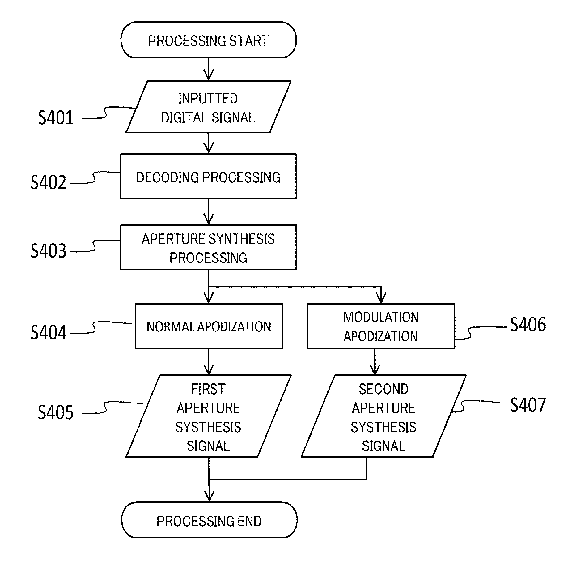
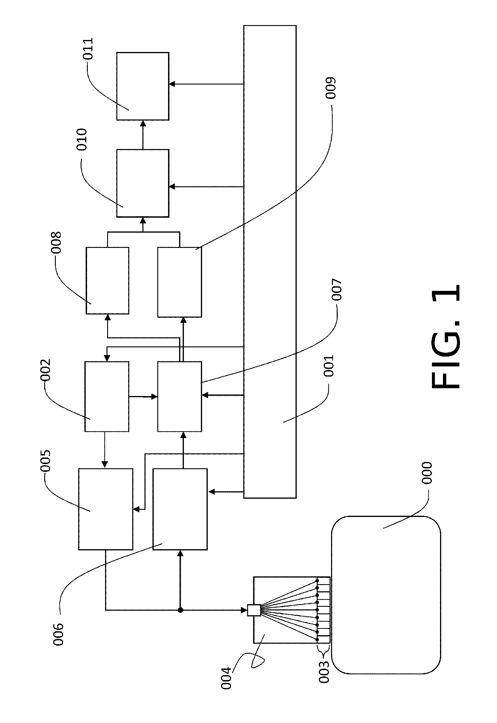
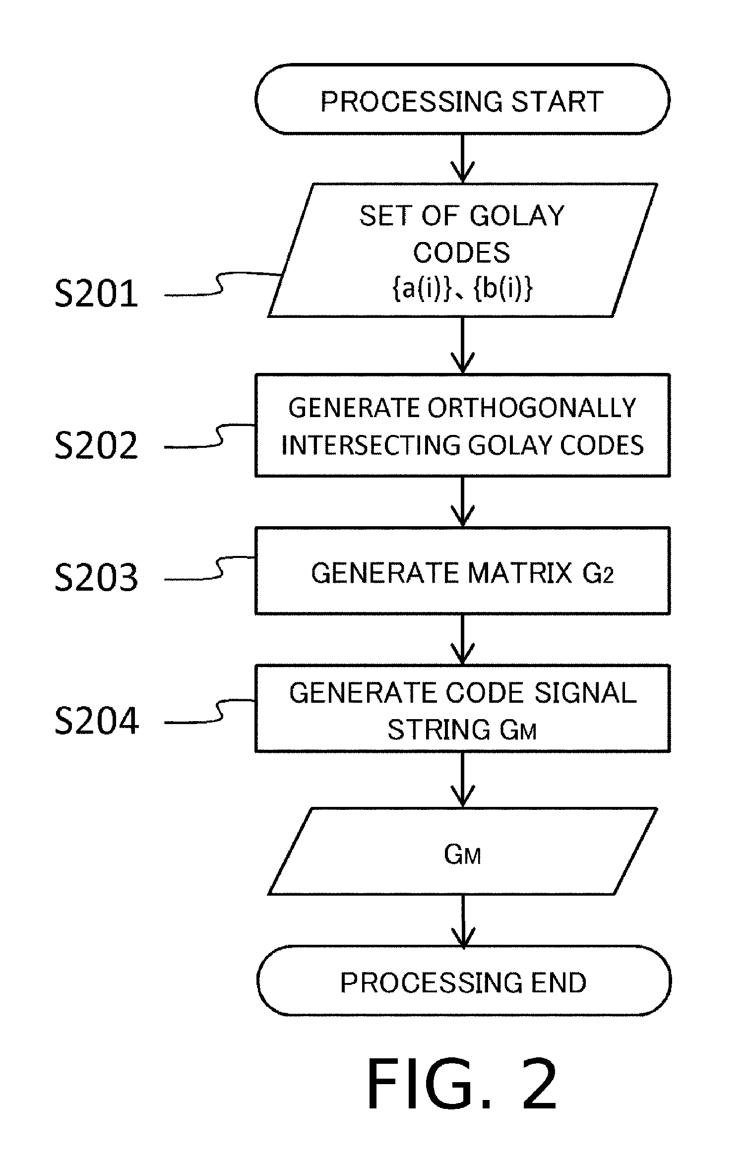
Disclosed is an apparatus that transmits an elastic wave to an object and receives a reflected wave, this apparatus including: a transmitting and receiving unit having elements for converting an elastic wave to an electric signal, and being arranged at least in one direction; an element controlling unit that inputs an electric signal to the element and causes the element to transmit an elastic wave; and a detecting unit that detects a reflected wave to be received by the element, wherein the electric signal to be inputted to the element is an encoded pulse signal encoded among the elements, and the detecting unit decodes the reflected wave and executes at different time points aperture synthesis processing of synthesizing the decoded reflected wave with respect to the intersections of two axes at different time points.

Description

TECHNICAL FIELD[0001]The present invention relates to an object information acquiring apparatus using an ultrasound wave.BACKGROUND ART[0002]Generally an ultrasound diagnostic apparatus not only displays an ultrasonographic image (a B-mode image) which visualizes a structure inside a bio-tissue based on a reflected wave that shows acoustic impedance distribution in tissue, but also has a function to visualize the blood flow and motion of tissues.[0003]Also recently estimating the hardness of a tissue portion in use of ultrasound waves has begun, and data thus obtained is used for diagnosing tissue. A strain inside the tissue, generated by such a method as applying static pressure from the surface of the body or applying excitation using a relatively low frequency ultrasound waves, is measured using ultrasound waves, and hardness of the tissue is estimated based on the amount of the strain. To calculate this strain, the displacement distribution of each point, measured with the ultra...

Claims


Application Information

Patent Timeline
Patent Type & Authority Patents(United States)
IPC IPC(8): G01N29/36G01N29/34G01N29/44G01S7/52A61B5/00G01S15/89A61B8/08
CPCG01N29/36A61B8/485A61B8/5207G01N29/34G01N29/44G01S7/52042G01S15/8959G01S15/8977G01S7/5209G01S7/52085
Inventor NAGAE, KENICHIKONDO, KENGOYAMAKAWA, MAKOTOSHIINA, TSUYOSHI
Owner CANON KK
Why Eureka
Try Eureka