
Optical transceiver and data mapping method using thereof

a technology of optical transceivers and data mapping methods, applied in electromagnetic transceivers, digital transmission, coding, etc., can solve the problems of increased probability of generating transmission errors, loss of optical signals, and difficulty in accepting packet signals of ethernet or the lik

Active Publication Date: 2016-11-01
OPTOELECTRONICS SOLUTIONS
View PDF8 Cites 2 Cited by
  • Summary
  • Abstract
  • Description
  • Claims
  • Application Information

AI Technical Summary

Benefits of technology

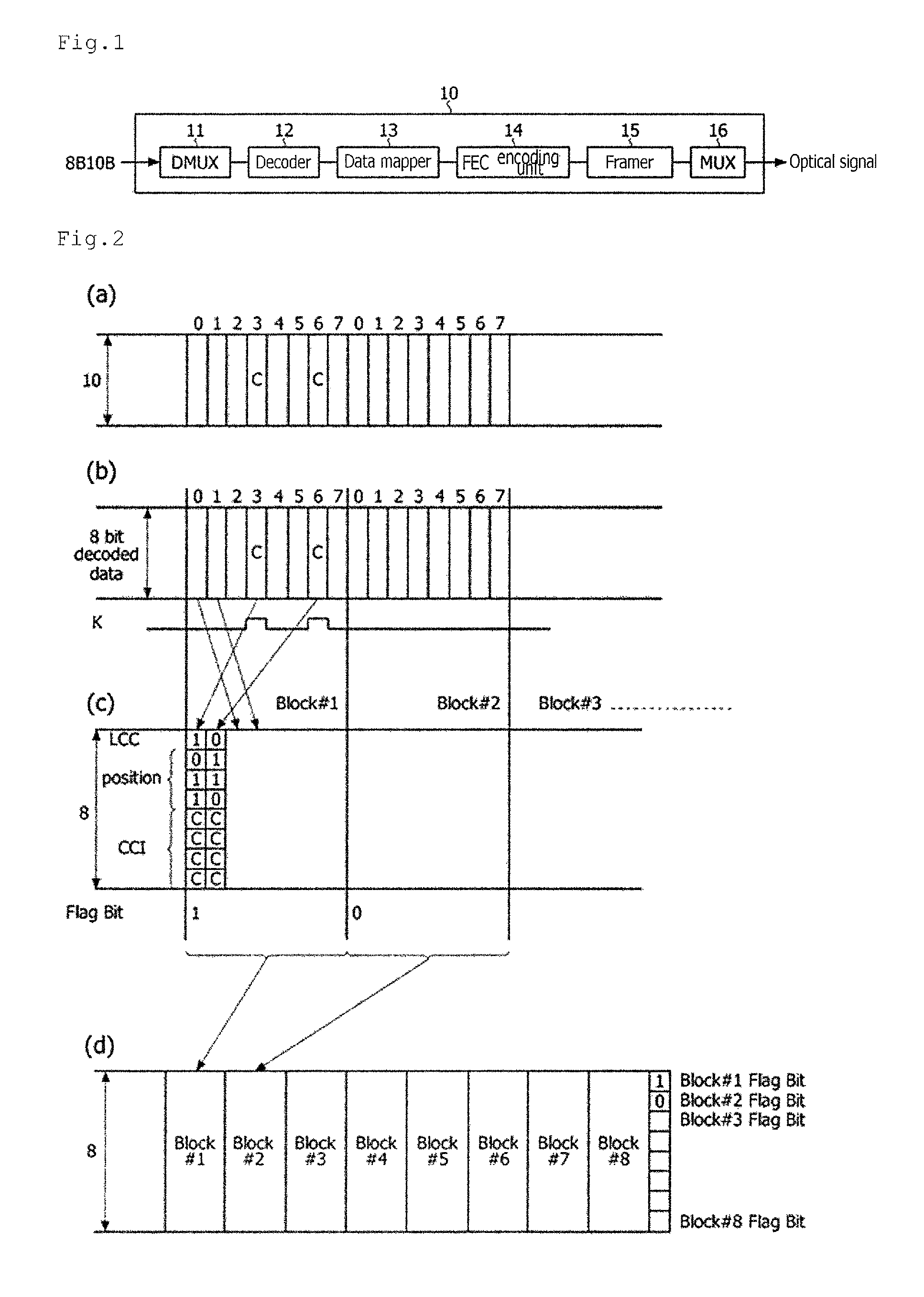
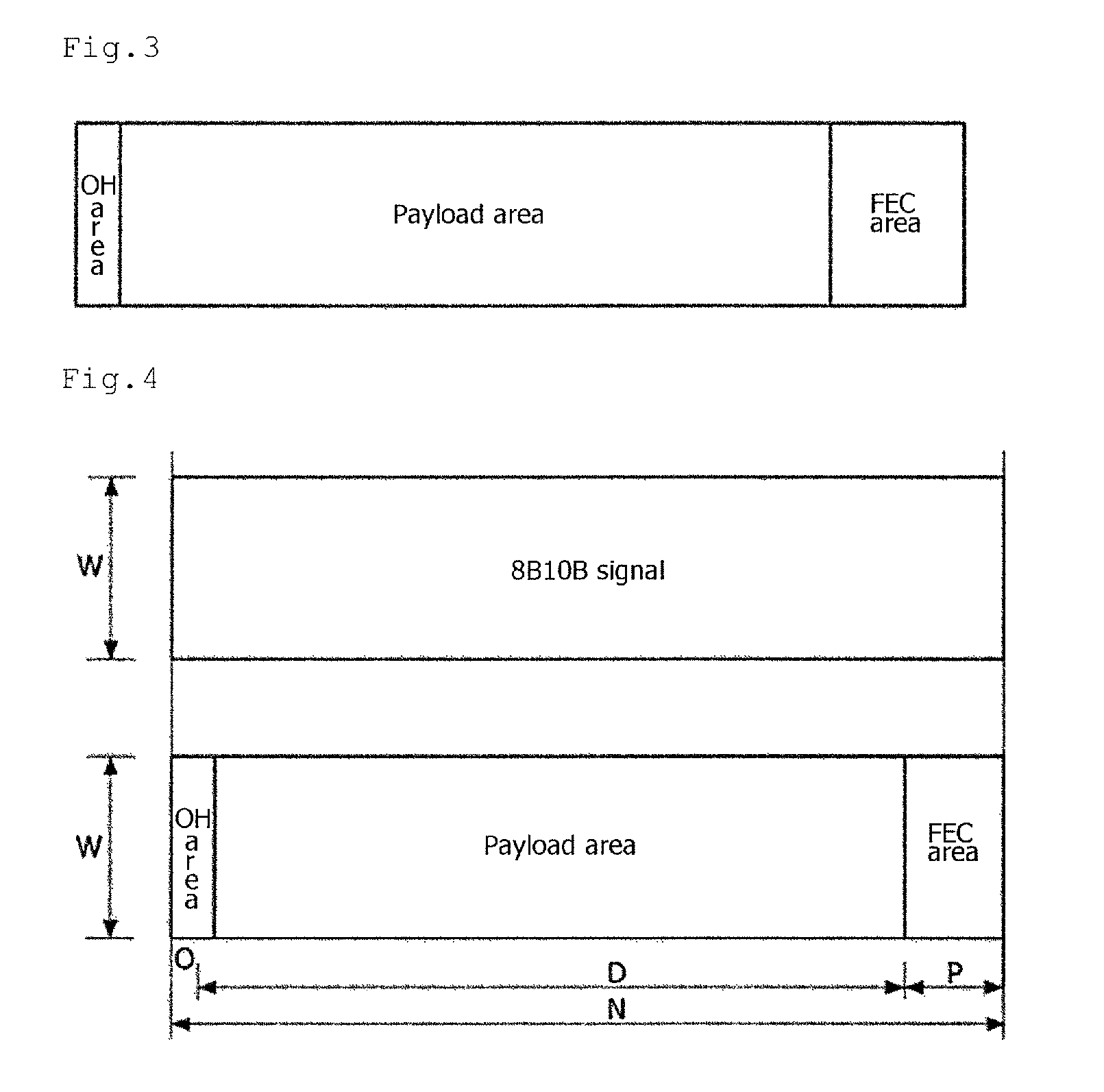
[0013]Therefore, the present invention has been made in view of the above problems, and it is an object of the present invention to provide an optical transceiver for providing a frame structure capable of performing Forward Error Correction (FEC) without degrading transmission speed or changing bandwidth, and a data mapping method using thereof.

Problems solved by technology

Meanwhile, since a SONET / SDH system mainly for long haul transmission basically defines a digital hierarchy for the sake of voices, it is difficult to accept packet signals of the Ethernet or the like.
Most of Common Public Radio Interface signals are transmitted through an optical fiber cable, and transmission distance thereof is some tens of kilometers in average, and since a large number of optical connectors or the like are used by the nature of network configuration, loss of optical signals is increased, and thus probability of generating a transmission error is increased.

Method used


Image

  • Optical transceiver and data mapping method using thereof
  • Optical transceiver and data mapping method using thereof
  • Optical transceiver and data mapping method using thereof

Examples


Embodiment Construction

[0049]As the present invention allows for various changes and numerous embodiments, particular embodiments will be illustrated in the drawings and described in detail in the written description. However, this is not intended to limit the present invention to particular modes of practice, and it is to be appreciated that all changes, equivalents, and substitutes that do not depart from the spirit and technical scope of the present invention are encompassed in the present invention.

[0050]It will be understood that, although the terms including ordinal numbers such as first, second, etc. may be used herein to describe various elements, these elements should not be limited by these terms. These terms are only used to distinguish one element from another. For example, a first element could be termed a second element, and, similarly, a second element could be termed a first element, without departing from the scope of example embodiments. As used herein, the term “and / or” includes any and...


PUM


Abstract

Disclosed is an optical transceiver. The optical transceiver includes a decoder for decoding an 8B10B line-coded signal; a data mapper for separating the decoded signal into block units and securing extra memory capacity by mapping a data code and a block information code onto each of the separated blocks; and an FEC encoding unit for creating a Forward Error Correction (FEC) data and mapping the FEC data onto the extra memory capacity.

Description

BACKGROUND OF THE INVENTION[0001]Field of the Invention[0002]The present invention relates to an optical transceiver and a data mapping method using thereof.[0003]Background of the Related Art[0004]Ethernet is initially used as a method of connecting and communicating a plurality of computers with each other in an office or a small space, and such a communication network is frequently referred to as a Local Area Network (LAN).[0005]Since the Ethernet generally performs data communications using a shared medium, a Media Access Control (MAC) protocol should be performed, and a CSMA / CD method defined in IEEE 802.3 is used in a wired Ethernet.[0006]Although a 10 Mbps or 100 Mbps class Ethernet is the mainstream in the initial stage, transmission speed thereof has been increased at an incredibly rapid pace in the last several years, and standardization of a 100G Ethernet beyond gigabit Ethernets has been completed and put into use currently.[0007]In addition, the Ethernet is used even in...

Claims


Application Information

Patent Timeline
Patent Type & Authority Patents(United States)
IPC IPC(8): H03M13/00H04L1/00
CPCH04L1/0041H04B10/40H04L1/0045
Inventor SEO, WANSEOKKIM, JONG HOPARK, MOON SOOYU, JOON SANG
Owner OPTOELECTRONICS SOLUTIONS
Learn More