Cylinder block arrangement with an exhaust gas system

a technology of exhaust gas and cylinder block, which is applied in the direction of engines, mechanical equipment, machines/engines, etc., can solve the problems of logistical problems, high cost, and inability to place near the engine, and achieve the effect of reducing temperature and pressure losses

Active Publication Date: 2016-11-08
DAIMLER AG
View PDF14 Cites 2 Cited by
  • Summary
  • Abstract
  • Description
  • Claims
  • Application Information

AI Technical Summary

Benefits of technology

[0002]Engine block arrangements are already known in which components of the exhaust gas system are situated near an engine block. An article in Motortechnische Zeitschrift (MTZ), 10, 2011, pages 762-768 describes an engine block arrangement having an exhaust gas system of a diesel engine that includes an oxidation catalytic converter and a particle filter. Both elements are jointly situated in a housing on one side of the engine block. This has the advantage that these elements reach their operating temperature very quickly, and that heat losses from the exhaust gas, which occur over a fairly long distance from the engine to the components, may be kept low. The known exhaust gas system has only two components having exhaust emission control activity situated near the engine. In more complex exhaust gas systems, in particular those having an additional catalytic converter for a selective catalytic reaction (SCR catalytic converter), placement near the engine is typically not possible due to installation space reasons. An SCR catalytic converter is used to reduce nitrogen oxides (NOx), in particular in the exhaust gas of diesel internal combustion engines. For this purpose, a urea-water solution is introduced into the exhaust gas flow in the area of a mixing section, the mixing section being used to thoroughly mix the urea-water solution with the exhaust gas and as a reaction section, along which the urea reacts with the water to form ammonia and carbon dioxide. The ammonia in turn reacts in the SCR catalytic converter with the nitrogen oxides of the exhaust gas flow, thus lowering the nitrogen oxides concentration. The mixing section must have a certain length to ensure its functioning. For this reason, the SCR catalytic converter is typically situated in a vehicle underbody area in order to provide a sufficiently long path for the exhaust gas flow from the engine block to the SCR catalytic converter. This has the disadvantage that temperature and pressure losses occur in the exhaust gas flow. In addition, a sensor system for adding the urea-water solution as well as for the SCR catalytic converter must be laboriously mounted and connected to the vehicle electronics system. Furthermore, the arrangement of the components in the vehicle underbody area depends on the vehicle type, so that a large number of exhaust gas system variants is necessary, which entails logistical problems and high costs.
[0020]Lastly, the engine block arrangement can have the particle filter and the SCR catalytic converter situated substantially below the exhaust gas turbocharger and also substantially below the oxidation catalytic converter. This means a particularly compact arrangement of the components, which logically are situated close to one another in order to minimize temperature and pressure losses. The components are preferably situated next to one another in pairs, namely, the exhaust gas turbocharger and the oxidation catalytic converter on the one hand and the particle filter and the SCR catalytic converter on the other hand.

Problems solved by technology

In more complex exhaust gas systems, in particular those having an additional catalytic converter for a selective catalytic reaction (SCR catalytic converter), placement near the engine is typically not possible due to installation space reasons.
This has the disadvantage that temperature and pressure losses occur in the exhaust gas flow.
In addition, a sensor system for adding the urea-water solution as well as for the SCR catalytic converter must be laboriously mounted and connected to the vehicle electronics system.
Furthermore, the arrangement of the components in the vehicle underbody area depends on the vehicle type, so that a large number of exhaust gas system variants is necessary, which entails logistical problems and high costs.
However, this compact arrangement per se is still provided in the vehicle underbody area, resulting in the corresponding disadvantages.
This results in additional installation space for the arrangement of the exhaust gas system at the engine block.

Method used


Image

  • Cylinder block arrangement with an exhaust gas system
  • Cylinder block arrangement with an exhaust gas system
  • Cylinder block arrangement with an exhaust gas system

Examples


Embodiment Construction

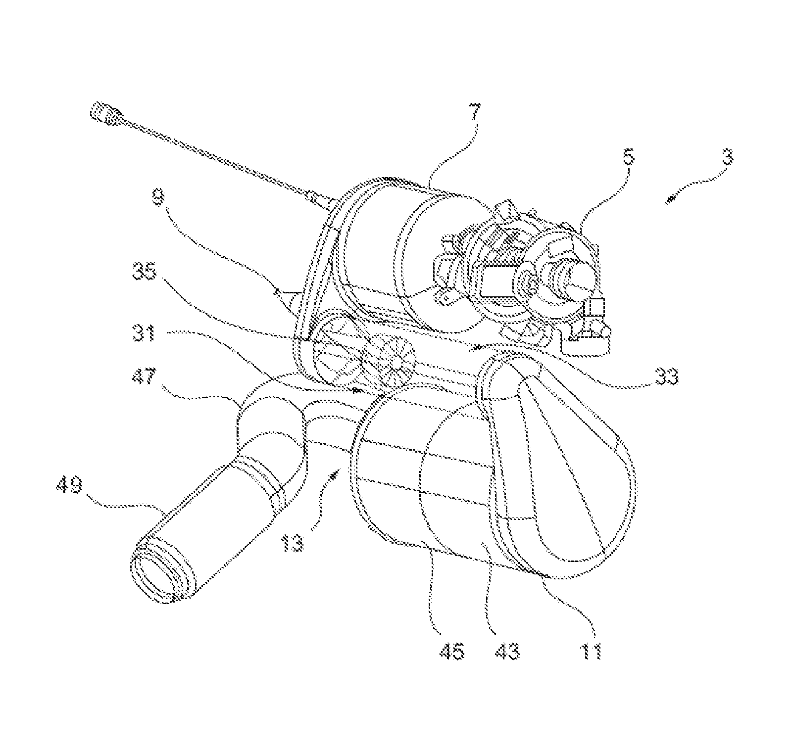
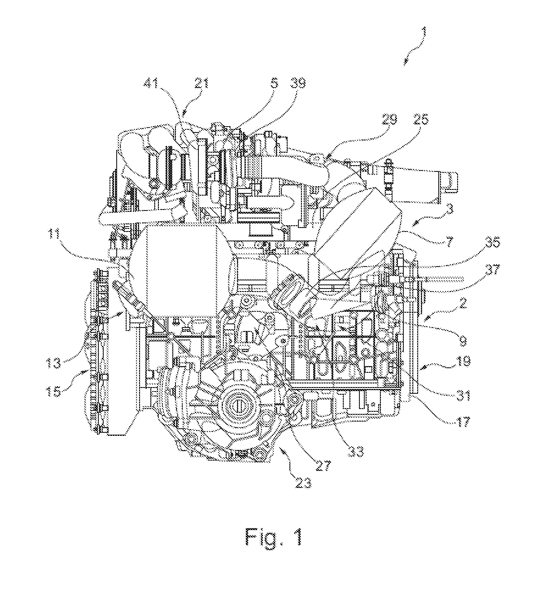
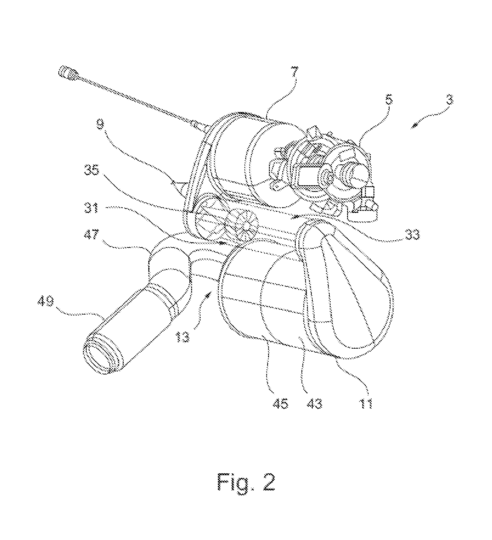
[0024]FIG. 1 shows a schematic view of a first exemplary embodiment of an engine block arrangement 1 having an engine block 2 and an exhaust gas system 3. The exhaust gas system, viewed in the flow direction of an exhaust gas flow from the engine block 2 to an exhaust (not illustrated), includes an exhaust gas turbocharger 5, an oxidation catalytic converter 7, a feed device 9 for urea-water solution, a particle filter, and an SCR catalytic converter situated one behind the other, the latter two components being situated together in a container 11, also referred to as a combi-box, and also includes a joint 13 for connecting a pipe connection, not illustrated, which leads to a muffler, likewise not illustrated, and lastly, to an exhaust. A decoupling element, not illustrated, is preferably provided directly in the connection to the joint 13 in order to vibrationally decouple the parts situated downstream, viewed in the flow direction of the exhaust gas, from the components of the exh...


PUM


Abstract

An engine block arrangement includes an engine block and an exhaust gas system. The exhaust gas system, viewed in the flow direction of an exhaust gas flow, includes an exhaust gas turbocharger, an oxidation catalytic converter, a feed device for a urea-water solution, a particle filter, and an SCR catalytic converter arranged one behind the other. The exhaust gas turbocharger, the oxidation catalytic converter, the feed device for the urea-water solution, the particle filter, and the SCR catalytic converter are situated together on the engine block along one side thereof, the side being oriented essentially perpendicularly with respect to an output side of the engine block.

Description

BACKGROUND AND SUMMARY OF THE INVENTION[0001]Exemplary embodiments of the invention relate to an engine block arrangement having an exhaust gas system.[0002]Engine block arrangements are already known in which components of the exhaust gas system are situated near an engine block. An article in Motortechnische Zeitschrift (MTZ), 10, 2011, pages 762-768 describes an engine block arrangement having an exhaust gas system of a diesel engine that includes an oxidation catalytic converter and a particle filter. Both elements are jointly situated in a housing on one side of the engine block. This has the advantage that these elements reach their operating temperature very quickly, and that heat losses from the exhaust gas, which occur over a fairly long distance from the engine to the components, may be kept low. The known exhaust gas system has only two components having exhaust emission control activity situated near the engine. In more complex exhaust gas systems, in particular those ha...

Claims


Application Information

Patent Timeline
Patent Type & Authority Patents(United States)
IPC IPC(8): F01N5/04F01N13/02F01N3/035F01N3/021F02B37/00F01N3/20F01N3/10F01N13/00
CPCF01N13/001F01N3/021F01N3/035F01N3/103F01N3/106F01N3/2066F01N13/009F01N13/0097F01N13/02F02B37/00F01N2250/02F01N2340/02F01N2340/06F01N2610/02F01N2610/1453Y02T10/24Y02A50/20Y02T10/12
Inventor SPENGEL, CHRISTOPHPEPE, ANTONIORAITSCHEV, PETERMUELLER, JUTTA ELISABETHSCHUBERT, CLEMENS
Owner DAIMLER AG
Why Eureka
Try Eureka