Electrical connector structure

a technology of electrical connectors and connectors, applied in the direction of coupling devices, two-part coupling devices, electrical equipment, etc., can solve the problems of electrical signals originally transmitted to generate noise, and achieve the effect of reducing high frequency electromagnetic nois

Active Publication Date: 2016-11-15
SPEED TECH
View PDF11 Cites 25 Cited by
  • Summary
  • Abstract
  • Description
  • Claims
  • Application Information

AI Technical Summary

Benefits of technology

[0010]A primary object of the present invention is to provide an electrical connector structure, and more particularly, to provide an electrical connector structur

Problems solved by technology

However, with the trend of miniaturization of the electronic devices, the electrical signals are likely to cause crosstalk, thus causing the electrical signals originally transmitted to generate noises.
However, in the above disclosures of US Patent Number U.S. Pat. No. 8,808,029 and Taiwan Utility Model Patent Number M299955, when the ground terminals in the upper a

Method used


Image

  • Electrical connector structure
  • Electrical connector structure
  • Electrical connector structure

Examples


first embodiment

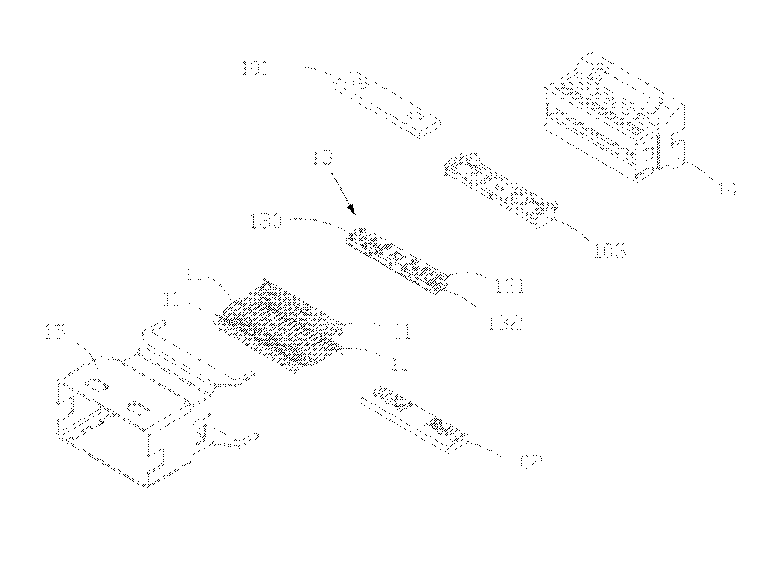
[0031]The signal terminals 12 of the present invention are plural pairs of differential signal terminals, which are used to transmit high frequency electrical signals in a differential mode. Each of the signal terminals 12 is arranged between the ground terminals 11, and the ground terminals 11 may electrically contact a docking connector (not shown) or a grounding circuit to form a grounding path, so as to reduce a noise interference generated when the signal terminals 12 transmit signals. In the present invention, the ground terminals 11 and the signal terminals 12 are fixed on the insulating body 10 and arranged on two opposite sides of the divider block 103. Each of the signal terminals 12 and the ground terminals 11 has a docking portion 110 and 120, a main portion 111 and 121, and a tail portion 112 and 122. The main portions 111 and 121 are respectively connected to the docking portions 110 and 120 and the tail portions 112 and 122. Each of the main portions 111 and 121 is fi...

second embodiment

[0042]As shown in FIGS. 11-15, an electrical connector structure 1 of the present invention is provided, and includes an insulating body 10, ground terminals 11, signal terminals 12, and a grounding piece 13. The insulating body 10 is formed from a first insulator 101, a second insulator 102, and a divider block 103. The ground terminals 11 and the signal terminals 12 are fixed on the insulating body 10 and arranged on two opposite sides of the divider block 103. Each of the signal terminals 12 and the ground terminals 11 has a docking portion 110 and 120, a main portion 111 and 121, and a tail portion 112 and 122. The main portions 111 and 121 are respectively connected to the docking portions 110 and 120 and the tail portions 112 and 122. Each of the main portions 111 and 121 is fixed on the insulating body 10. Each of the docking portions 110 and 120 and each of the tail portions 112 and 122 extend from two sides of the insulating body 10.

[0043]In the second embodiment of the pre...


PUM


Abstract

An electrical connector structure includes an insulating body, ground terminals, and a grounding piece. The insulating body has a divider block. The ground terminals are fixed on the insulating body and arranged in two opposite sides of the divider block. Each ground terminal has a docking portion, a main portion, and a tail portion. The main portions are fixed on the insulating body. The docking portions and the tail portions extend from two sides of the insulation body. The grounding piece is fixed on the divider block. The grounding piece has a first mounting plane and a second mounting plane corresponding to the first mounting plane. The first mounting plane and the second mounting plane are located at two opposite surfaces of the divider block, and have contact portions protruding therefrom. The contact portions electrically contact the ground terminals respectively.

Description

RELATED APPLICATIONS[0001]This application claims priority to Taiwan Application Serial Number 104213229, filed Aug. 17, 2015, which is herein incorporated by reference.BACKGROUND[0002]Field of Invention[0003]The present invention relates to an electrical connector structure. More particularly, the present invention relates to an electrical connector structure which is capable of reducing high frequency electromagnetic noises.[0004]Description of Related Art[0005]Due to the amount of data transmitted between electrical devices continues to increase, the signal transmitting speeds between the electrical devices also increase accordingly, thereby providing users with more user friendly experience. In order to allow the users to transmit a large amount of electrical data within a shorter period of time, apart from increasing the gateways of transmitting electrical signals between the electrical devices, a conventional countermeasure is to increase an electrical signal transmitting freq...

Claims


Application Information

Patent Timeline
IPC IPC(8): H01R13/6597H01R13/6471H01R24/76
CPCH01R13/6471H01R24/76H01R13/6597H01R24/60
Inventor CHANG, HAO-CHECHEN, CHIH-CHENG
Owner SPEED TECH
Why Eureka
Try Eureka