

Equipment and method for detecting temperature coefficient of remanence
A technology of temperature coefficient and detection equipment, which is applied in the direction of magnetic performance measurement, etc., can solve the problems of low precision, small magnetic flux signal, and inability to meet the detection requirements of low temperature coefficient and ultra-low temperature coefficient, so as to reduce electromagnetic noise and improve signal noise than the effect
Active Publication Date: 2012-06-27
CENT IRON & STEEL RES INST
View PDF6 Cites 13 Cited by
- Summary
- Abstract
- Description
- Claims
- Application Information
AI Technical Summary
Problems solved by technology
[0011] There are two main problems in the open-circuit magnetic flux detection method in the prior art: first, the detection coil makes a one-way single movement relative to the sample to cut the magnetic force line, so the obtained magnetic flux signal is small, so it needs to be amplified by an amplifier before read by the integrator
For high-precision detection, the more intermediate processing links the signal undergoes, the more detection errors will be introduced; second, the influence of the geomagnetic field and other electromagnetic interference signals is not considered, and these are very important for low temperature coefficients, especially ultra-low temperature Accurate detection of coefficients (on the order of 1 / 10,000 to 1 / 100,000) is crucial
Therefore, the data error of the temperature coefficient of remanence measured by the existing technology is large, the accuracy is not high, and it cannot meet the detection requirements of low temperature coefficient and ultra-low temperature coefficient
Method used
View moreImage
Smart ImageViewing Examples


Examples
example 1
[0071] The sample S to be tested can be a low temperature coefficient 2:17 type samarium cobalt permanent magnet material. For each temperature point, such as 20 ° C and 100 ° C, the magnetic flux detection is carried out 6 times, and the detection results of each time are listed in Table 1 . It can be seen that each detection result is very close, that is, the drift of the remanence temperature coefficient detection device according to the exemplary embodiment of the present invention is small, and the signal-to-noise ratio is high. The open-circuit reversible remanence temperature coefficient α(B r ) is -2.2×10 -5 / °C.
Login to View More PUM
 Abstract
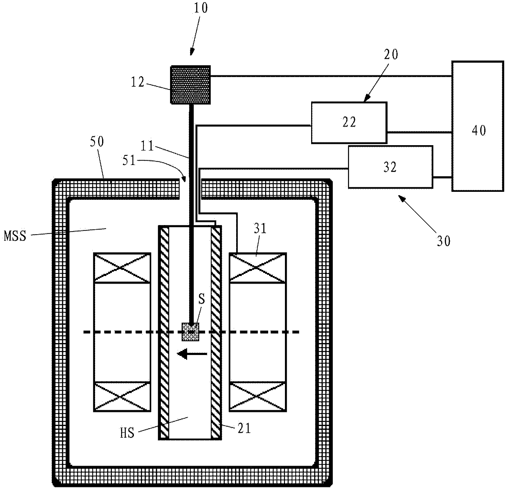
The invention provides equipment and method for detecting the temperature coefficient of remanence. The equipment comprises a rotating device for a sample to be detected, a temperature control device, a magnetic flux detecting device and a device for computing the temperature coefficient of the remanence. The rotating device for the sample to be detected is used for rotating the sample to be detected; the temperature control device is used for changing and stably maintaining the temperature of the sample to be detected; the magnetic flux detecting device is used for detecting different magnetic fluxes generated by different magnetic fields of the sample to be detected due to different temperatures while the sample to be detected is rotated; and the device for computing the temperature coefficient of the remanence is used for computing the temperature coefficient of the remanence of the sample to be detected according to the different magnetic fluxes corresponding to the different temperatures, detected by the magnetic flux detecting device. Therefore, the temperature coefficient of open-circuit remanence of permanent magnet materials with high signal to noise ratio can be obtained.
Description
technical field [0001] The invention belongs to the field of testing the magnetic properties of permanent magnet materials, and relates to a detection device and method for the temperature coefficient of open circuit remanence of permanent magnet materials. Background technique [0002] High-performance permanent magnet materials are widely used in gyroscopes and accelerometers in inertial navigation systems, microwave tubes for electronic vacuum devices, traveling wave tubes, klystrons and other high-precision instruments. The temperature stability of permanent magnet materials (reflected in the temperature coefficient of remanence) is one of the important indicators that affect the accuracy, accuracy and stability of high-precision instruments. Therefore, how to accurately measure the temperature coefficient of remanence α (B r ), it is particularly important to provide important data for the design and manufacture of high-precision instruments. [0003] The existing tech...
Claims
Login to View More Application Information
Patent Timeline
 IPC IPC(8): G01R33/12
Inventor 方以坤郭朝晖朱明刚李卫周栋潘伟
Owner CENT IRON & STEEL RES INST