Printing apparatus and driving method therefor

a printing apparatus and driving method technology, applied in the direction of printing, etc., can solve the problems of increasing manufacturing costs, limited nozzle arrays capable of printing dots on printing mediums, and inability to perform preliminary discharge on sheets by desired nozzles, etc., to achieve simple and low-end arrangement and maintain print speed

Active Publication Date: 2016-11-22
CANON KK
View PDF53 Cites 8 Cited by
  • Summary
  • Abstract
  • Description
  • Claims
  • Application Information

AI Technical Summary

Benefits of technology

[0010]The present invention provides a technique for a new driving method of two or more nozzle arrays, which is advantageous in performing preliminary discharge on a sheet while maintaining a print speed with a simple and low-end arrangement.

Problems solved by technology

This requires the user to change a design of hardware such as the circuit design of a printing apparatus along with a change in operation speed, leading to an increase in manufacturing cost.
Furthermore, in the arrangement described in Japanese Patent Laid-Open No. 2012-30594, when time-divisionally driving each nozzle array, one period of time-divisional driving corresponds to a plurality of column data, and thus a nozzle array capable of printing dots on the printing medium is limited (a nozzle array to be used is fixed for each pixel).
At this time, it may be impossible to perform preliminary discharge on sheet by a desired nozzle.
Therefore, if data for preliminary discharge in which only usable nozzles are selected are generated in advance and stored in the memory of the printing apparatus in order to make it possible to perform preliminary discharge on a sheet by all nozzles, a large-capacity memory is required to store data for preliminary discharge of the entire print region for each ink color or each nozzle array, leading to an increase in manufacturing cost.

Method used


Image

  • Printing apparatus and driving method therefor
  • Printing apparatus and driving method therefor
  • Printing apparatus and driving method therefor

Examples


first embodiment

[0073](2. First Embodiment)

[0074]The first embodiment will be described below with reference to FIGS. 5A to 13B.

[0075](2-1. Driving Method of Printing Apparatus)

[0076]FIGS. 5A to 5C are views for explaining an example of an image data processing method. FIG. 5A is a flowchart illustrating an example of the image data processing method. FIG. 5B is a block diagram for explaining a data flow corresponding to the flowchart.

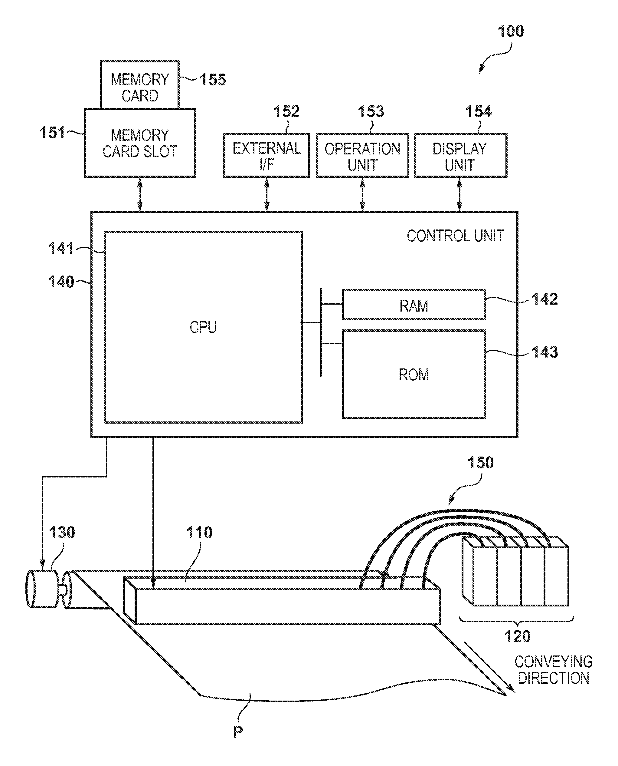
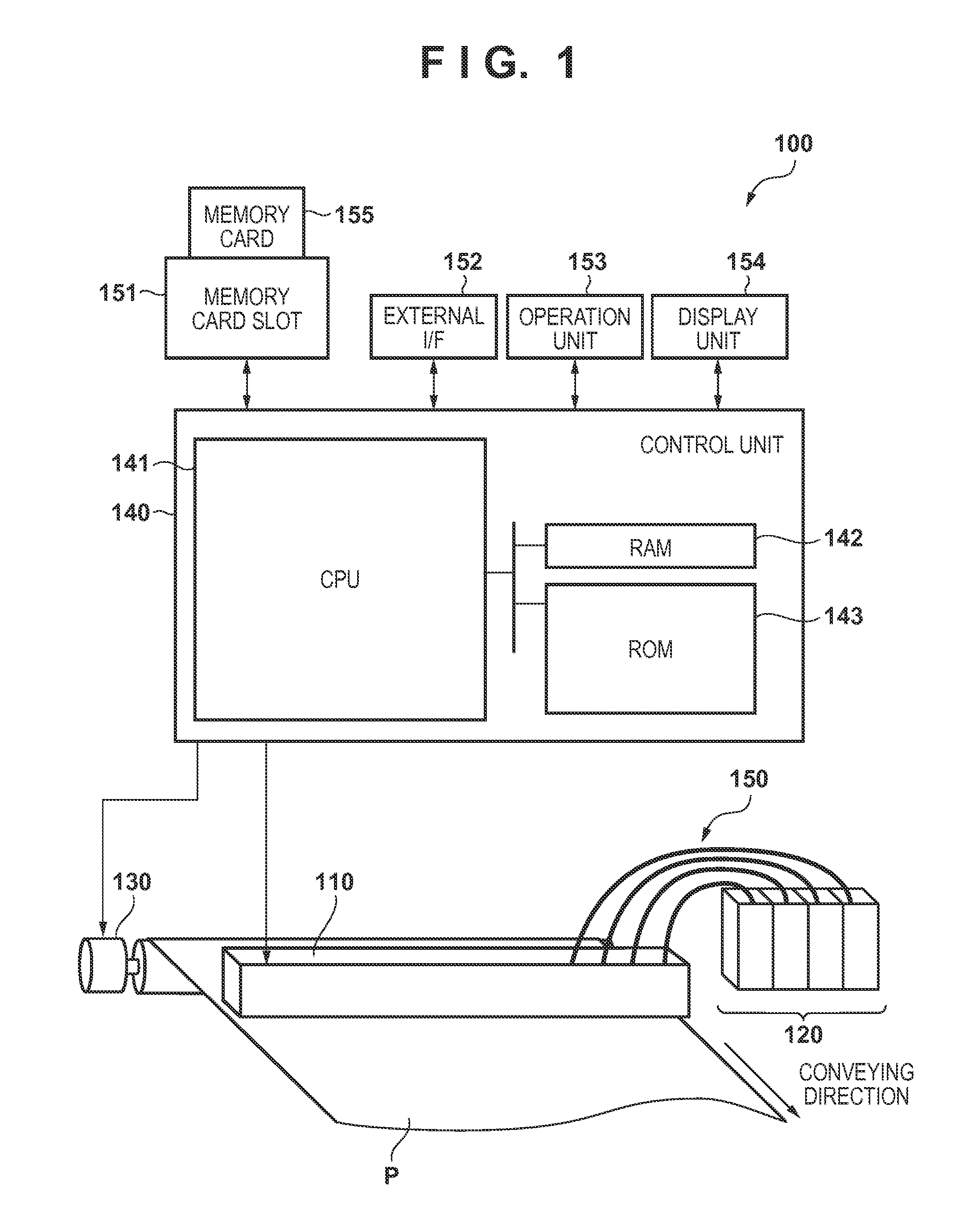
[0077]In step S110 (to be simply referred to as “S110” hereinafter; the same applies to other steps), image data input from a data input unit 510 are acquired. More specifically, as described with reference toFIG. 1, the image data can be externally input via an external interface 152 or the like, and expanded onto a RAM 142 of a control unit 140 or the like. The obtained image data are 8-bit, 256-tone data for three colors of red (R), green (G), and blue (B).

[0078]In S120, a color conversion processing unit 520 performs color conversion processing (color space conver...

second embodiment

[0151](3. Second Embodiment)

[0152]The second embodiment will be described with reference to FIGS. 14A, 14B, 15A, and 15B. A case in which the block driving order complies with the order of the block numbers has been exemplified in the above-described first embodiment for the sake of simplicity. The present invention, however, is not limited to this, and other block driving orders may be adopted. In this embodiment, the block driving order is not the order of block numbers, and complies with shuffled block numbers. Such driving method will also be referred to as “distributed driving” hereinafter.

[0153]FIG. 14A exemplifies data corresponding to a restriction pattern TR2a according to this embodiment, similarly to FIG. 12A. FIG. 14B exemplifies portions corresponding to four columns clm1 to clm4 of the data and a corresponding timing chart of driving nozzles, similarly to FIG. 12B.

[0154]In this embodiment, in the column clm1, nozzles nz of B#5, B#6, B#11, and B#16 are non-driving nozzl...

third embodiment

[0159](4. Third Embodiment)

[0160]The third embodiment will be described with reference to FIGS. 16, 17A, and 17B. A case in which the order of dots to be printed by preliminary discharge complies with the order of block numbers has been exemplified in the first and second embodiments for the sake of simplicity. However, the present invention is not limited to this, and the order of dots to be printed by preliminary discharge may be another order. In this embodiment, the order of dots to be printed by preliminary discharge is not the order of block numbers, and complies with shuffled block numbers.

[0161]Note that a pattern of dots to be printed by preliminary discharge in the first and second embodiments will be referred to as a “sequential pattern” hereinafter. To the contrary, a pattern of dots to be printed by preliminary discharge in this embodiment will be referred to as a “distributed pattern” hereinafter.

[0162]FIG. 16 shows an example of a distributed pattern according to this...


PUM


Abstract

A printing apparatus comprising a printhead including two nozzle arrays neighboring in a first direction, each including nozzles arrayed along a second direction, a conveying unit for conveying a sheet in the first direction, a driving unit for driving the printhead so that each nozzle performs preliminary discharge on the sheet, and a unit configured to perform selecting some nozzles as non-driving nozzles and the remaining nozzles as driving nozzles for every column data in image data, determining image data to be assigned to each array as a first data so that a dot corresponding the non-driving nozzle in one of the two arrays is printed by the driving nozzle in the other, determining data for preliminary discharge as a second data so that each driving nozzle performs preliminary discharge, and ORing the first and second data.

Description

BACKGROUND OF THE INVENTION[0001]1. Field of the Invention[0002]The present invention relates to a printing apparatus and a driving method therefor.[0003]2. Description of the Related Art[0004]A printing apparatus includes, for example, a printhead for printing on a printing medium, and a conveying roller for conveying the printing medium. A plurality of nozzles for printing dots by discharging ink are provided in an inkjet printhead, and each nozzle performs preliminary discharge at a predetermined interval. Preliminary discharge is one of recovery processes of the printhead to prevent clogging of each nozzle. Since nozzles whose driving frequency is relatively low can appropriately print dots by performing preliminary discharge, the quality of an image formed on a printing medium is improved.[0005]Japanese Patent Laid-Open No. 2005-246643 discloses a technique of performing “preliminary discharge on a sheet” to print dots by preliminary discharge on a printing medium at a density ...

Claims


Application Information

Patent Timeline
Patent Type & Authority Patents(United States)
IPC IPC(8): B41J2/165
CPCB41J2/16585B41J2/16526B41J2002/1657B41J2002/16529
Inventor KANO, YUTAKAKAWATOKO, NORIHIROSUZUKI, FUMIKO
Owner CANON KK
Why Eureka
Try Eureka