Charge pump with suppressed feedthrough effect

a charge pump and feedthrough effect technology, applied in the field of electronic circuit technology, can solve the problems of many limitations of conventional charge pumps, and achieve the effects of reducing the feedthrough effect, reducing the die area of the charge pump, and reducing the capacitance of decoupling at the gate terminal

Active Publication Date: 2016-11-22
SEMICON MFG INT (SHANGHAI) CORP
View PDF9 Cites 2 Cited by
  • Summary
  • Abstract
  • Description
  • Claims
  • Application Information

AI Technical Summary

Benefits of technology

[0006]In embodiments of the invention, a capacitor is introduced at the gate terminals of the switch transistor and the current source transistor to provide a feedback path that is opposite to an existing feedback path, such that the feedthrough is suppressed. Because of the reduced feedthrough effect, the decoupling capacitance at the gate terminal can be reduced, decreasing the die area of the charge pump. In some embodiments, the suppression of feedthrough can occur when the current source transistor is in the saturation region, resulting in a greater range of charge pump output voltage. In some embodiments, a mismatch between charge pump charging and discharging currents caused by feedthrough effects can be suppressed, and spurs in the PLL are reduced.
[0007]According to some embodiments of the present invention, a charge pump circuit includes a capacitor, a current source circuit coupled to the capacitor for providing a charging current and a discharging current to the capacitor. The current source circuit includes a switch transistor with a gate terminal for receiving a control signal, a current source transistor having a source terminal coupled to a drain of the switch transistor, and a feedthrough suppression capacitor coupled between a gate terminal of a gate terminal of the switch transistor and a gate terminal of the current source transistor. The feedthrough suppression capacitor is configured to lower a feedthrough effect.
[0010]According to some embodiments of the present invention, a phase locked loop (PLL) circuit includes a phase detector, a charge pump circuit coupled to the phase detector, a low-pass filter coupled to the charge pump circuit, a voltage-controlled oscillator (VCO) coupled to the low-pass filter, and a frequency divider coupled between the VCO and the phase detector. The charge pump circuit includes a capacitor and a current source circuit coupled to the capacitor for providing a charging current and a discharging current to the capacitor. The current source circuit includes a switch transistor with a gate terminal for receiving a control signal, a current source transistor having a source terminal coupled to a drain of the switch transistor, and a feedthrough suppression capacitor coupled between a gate terminal of the switch transistor and a gate terminal of the current source transistor. The coupling element is configured to lower a feedthrough effect.

Problems solved by technology

However, conventional charge pumps suffer from many limitations, as will be described below.

Method used


Image

  • Charge pump with suppressed feedthrough effect
  • Charge pump with suppressed feedthrough effect
  • Charge pump with suppressed feedthrough effect

Examples


Embodiment Construction

[0020]Various embodiments of the present invention are described below. It should be noted that, when appropriate, the exemplary embodiments and features can be combined with each other.

[0021]A charge pump is an important component in a PLL (Phase-Locked Loop, abbreviated to PLL). The charge pump provides a high loop gain of the circuit, so that, when the PLL is phase locked, the phase difference between the input and the output of the frequency divider is zero. It can reduce the variation of control signals in the voltage-controlled oscillator (VCO) and reduce output spurs (Spur).

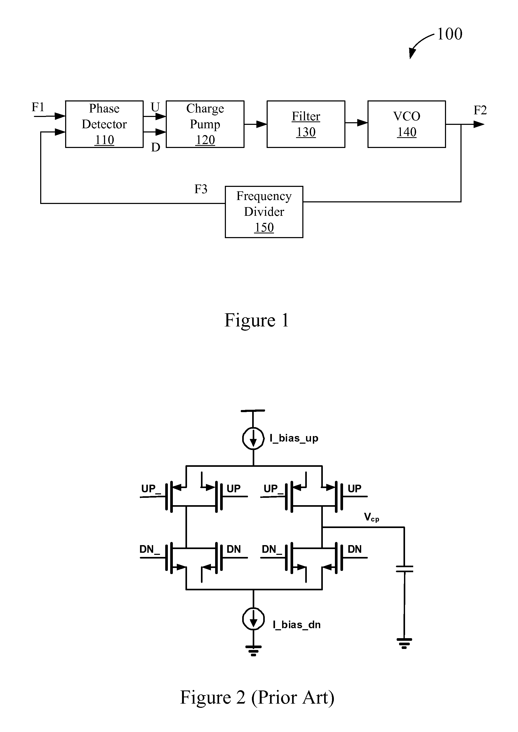
[0022]FIG. 1 is a simplified block diagram of a phase locked loop (PLL) according to an embodiment of the present invention. As shown in FIG. 1, phase locked loop 100 includes a phase detector 110, a charge pump circuit 120, a low-pass filter (LPF) 130, a voltage-controlled oscillator (VCO) 140, and a frequency divider 150.

[0023]The output of charge pump circuit 120 is connected to low-pass filter 130, whi...


PUM


Abstract

A charge pump circuit includes a capacitor, a current source circuit coupled to the capacitor for providing a charging current and a discharging current to the capacitor. The current source circuit includes a switch transistor with a gate terminal for receiving a control signal, a current source transistor having a source terminal coupled to a drain of the switch transistor, and a feedthrough suppression capacitor coupled between a gate terminal of a gate terminal of the switch transistor and a gate terminal of the current source transistor. The feedthrough suppression capacitor is configured to lower a feedthrough effect.

Description

CROSS-REFERENCES TO RELATED APPLICATIONS[0001]This application claims priority to Chinese patent application No. 201410483106.1, filed on Sep. 19, 2014, the content of which is incorporated herein by reference in its entirety. This application is also related to U.S. Pat. No. 6,255,872 to Harada et. al., filed Mar. 26, 1999, the content of which is incorporated by reference herein in its entirety.BACKGROUND OF THE INVENTION[0002]The present invention relates to the field of electronic circuit technology; specifically it relates to a phase lock loop (PLL) circuit.[0003]A phase-locked loop (PLL) is a control system that generates an output signal whose phase is related to the phase of an input signal. In a simplified version, a PLL can be viewed as an electronic circuit having a variable frequency oscillator and a phase detector. The oscillator generates a periodic signal, and the phase detector compares the phase of that signal with the phase of an input periodic signal and adjusts t...

Claims


Application Information

Patent Timeline
Patent Type & Authority Patents(United States)
IPC IPC(8): H03L7/06H03L7/18H03L7/089H02M3/07
CPCH02M3/07H03L7/0891H03L7/18
Inventor ZHU, GUANGFENG, GUANG TAO
Owner SEMICON MFG INT (SHANGHAI) CORP
Why Eureka
Try Eureka