Distributed transconductance amplifier

a transconductance amplifier and distributed technology, applied in amplifiers, amplifiers with coupling networks, amplifiers with semiconductor devices/discharge tubes, etc., can solve the problems of large circuit board area, inability to implement, and high cost of external inductors, and achieve small die area and high transconductance

Active Publication Date: 2015-04-21
MACOM TECH SOLUTIONS HLDG INC
View PDF6 Cites 13 Cited by
  • Summary
  • Abstract
  • Description
  • Claims
  • Application Information

AI Technical Summary

Benefits of technology

[0007]The objects, features and advantages of the present invention include providing a distributed transconductance amplifier that may (i) provide broadband current into low impedance loads, (ii) provide high transconductance, (iii) occupy small die area, (iv) include bias injection circuits and / or (v) be implemented as an integrated circuit.

Problems solved by technology

The conventional methods are effective, but external inductors are expensive and occupy very large circuit board area in cases where the amplifier extends to low frequencies.
With uniform distributed amplifiers, the bias voltage on the output transmission line can also be applied through the output termination resistor if the current is relatively low, but cannot be implemented where no output line termination resistor is available.

Method used


Image

  • Distributed transconductance amplifier
  • Distributed transconductance amplifier
  • Distributed transconductance amplifier

Examples


Embodiment Construction

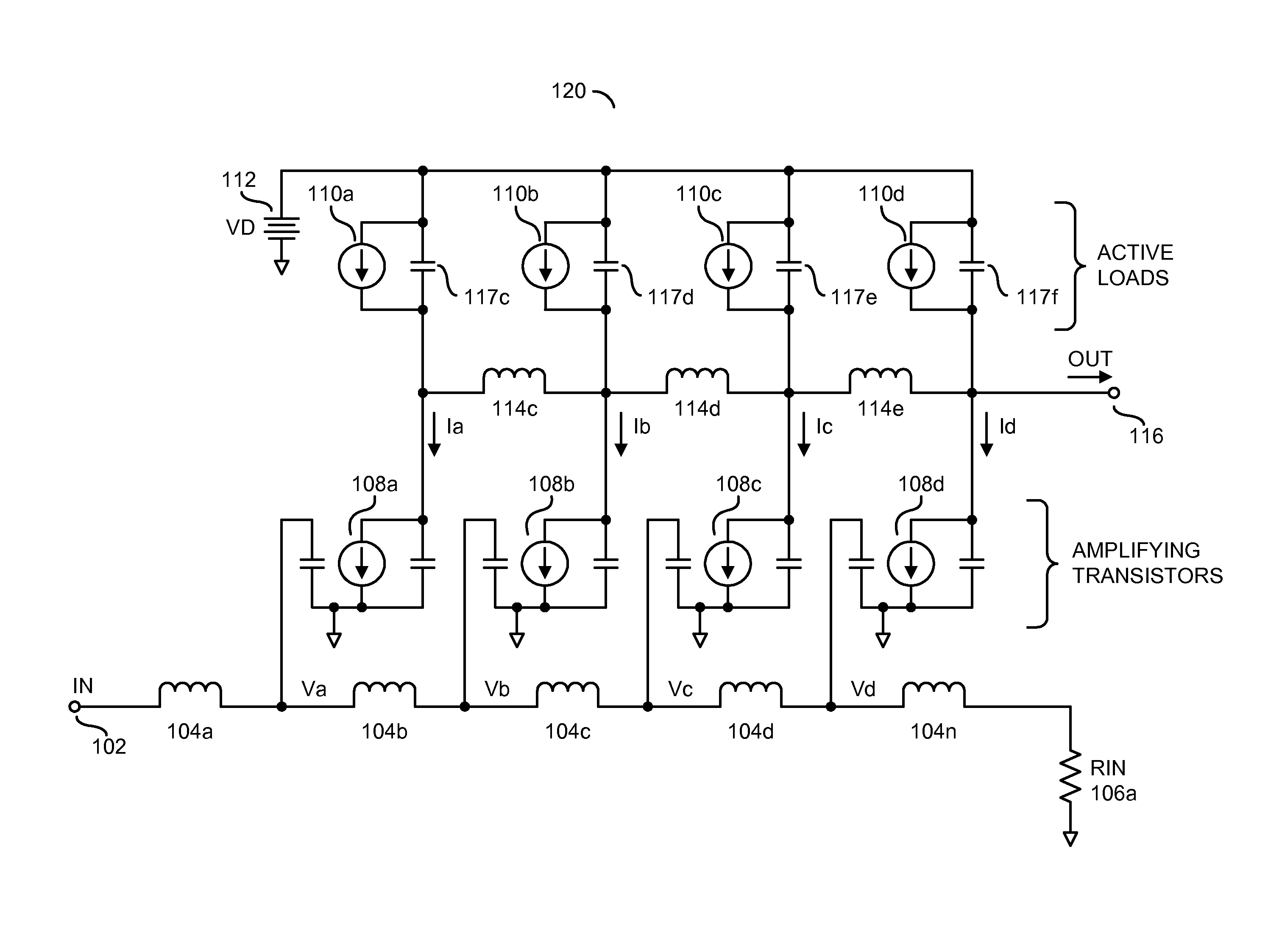
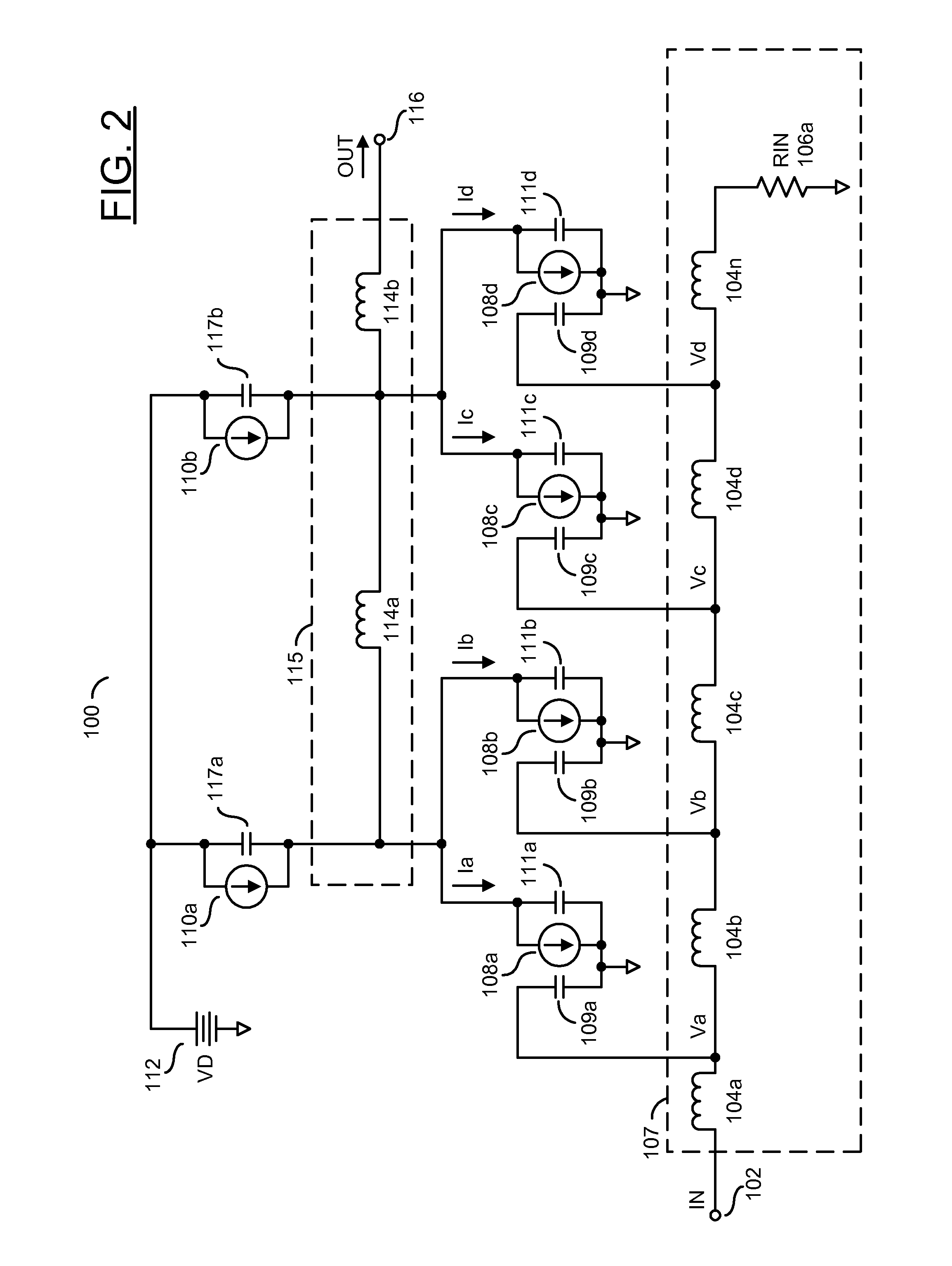
[0018]Embodiments of the present invention generally relate to non-uniform distributed amplifiers for transconductance applications. Transconductance amplification may amplify and convert an input voltage into an output current delivered into a load. The distributed amplifiers generally comprise multiple (e.g., four or more) non-uniform sections distributed between an input transmission line and an output transmission line. An impedance of the input transmission line may range from a few ohms (e.g., 5 ohms—Ω) to dozens of ohms (e.g., 50Ω) or more (e.g., 200Ω). An impedance of the output transmission line generally ranges from a few ohms (e.g., 10Ω) to multiple ohms (e.g., 50Ω). The amplifiers may include paired transistor outputs and one or more active current sources. The active current sources may be fabricated concurrently with the transistors and attached at the output nodes of the transistors to provide bias currents. The active bias circuits may be inserted at one or more node...


PUM


Abstract

An apparatus having an input transmission line, a plurality of amplifiers and an output transmission line is disclosed. The input transmission line may include a plurality of first inductors configured to receive an input voltage. The amplifiers may be configured to generate a plurality of intermediate currents by amplifying a plurality of intermediate voltages at a plurality of first nodes between the first inductors. The output transmission line generally includes a plurality of second inductors configured to generate an output current at an output node by combining the intermediate currents. Each of a plurality of second nodes connected to the second inductors may transfer a plurality of the intermediate currents. Each of the second inductors generally has a different one of a plurality of inductance values.

Description

[0001]This application relates to U.S. Provisional Application No. 61 / 825,633, filed May 21, 2013, which is hereby incorporated by reference in its entirety.FIELD OF THE INVENTION[0002]The present invention relates to high-frequency amplifiers generally and, more particularly, to a method and / or apparatus for implementing a distributed transconductance amplifier.BACKGROUND OF THE INVENTION[0003]Distributed amplifiers are commonly employed for ultra-broad bandwidth applications. The amplifiers achieve a broad bandwidth by absorbing parasitic elements of transistors into lowpass artificial input and output transmission lines with shunt capacitances mainly provided by the transistors and series inductors added by a designer. Common designs typically have a transistor per “section” and the amplified current from each section adds in phase at the output of the amplifiers.[0004]Referring to FIG. 1, a diagram of a conventional uniform distributed amplifier 90 is shown. Distributions in the...

Claims


Application Information

Patent Timeline
Patent Type & Authority Patents(United States)
IPC IPC(8): H03F3/60H03F3/193
CPCH03F3/193H03F3/605H03F3/60H03F3/607H03F2200/18
Inventor KENNAN, WAYNEMORKNER, HENRIK
Owner MACOM TECH SOLUTIONS HLDG INC
Why Eureka
Try Eureka