Methods and systems for decoupling the stabilization of two loops

a loop and stabilization technology, applied in the field of electronic circuits, can solve problems such as conflicting loop stability requirements, difficult to achieve, and undesirable reduction of slew rate, so as to reduce the area of die, reduce the need for capacitance, and reduce the effect of cos

Active Publication Date: 2006-11-14
TEXAS INSTR INC
View PDF10 Cites 16 Cited by
  • Summary
  • Abstract
  • Description
  • Claims
  • Application Information

AI Technical Summary

Benefits of technology

[0014]The invention provides technical advantages including but not limited to decoupling the stabilization of two loops within a circuit such that the required capacitance is small, and die area is reduced, resulting in some instances in lower costs. The inventions may be used with sensing loops including but not limited to applications requiring current sensing, temperature sensing, or monitoring other circuit parameters. These and other features, advantages, and benefits of the present invention can be understood by one of ordinary skill in the arts upon careful consideration of the detailed description of representative embodiments of the invention in connection with the accompanying drawings.

Problems solved by technology

Challenges can arise, however, when the loop stability requirements come into conflict.
However, this compensation capacitor Cx introduces trade-offs in the performance of the LDO 10.
There are at least two general classes of difficulties with this compensation approach.
The reduced slew rate is undesirable, as it degrades the transient response of the LDO 10.
Not only does the transient response suffer, but also the LDO 10 may become unstable.
Also, since N1 is a high impedance node, any capacitance may create a significant pole that would degrade stability.
A second set of difficulties arises for a three gain-stage LDO.
Additionally, the same trade-offs exist between the degradation of transient response and stability.
This potential solution is costly in terms of requiring a relatively large die area.
It has been determined that these and other problems result from the fact that the stability of the loops in the circuit are coupled in terms of stability requirements.
In this example, the capacitances affecting LDO stability and current limit stability inevitably affect one another.

Method used


Image

  • Methods and systems for decoupling the stabilization of two loops
  • Methods and systems for decoupling the stabilization of two loops
  • Methods and systems for decoupling the stabilization of two loops

Examples


Embodiment Construction

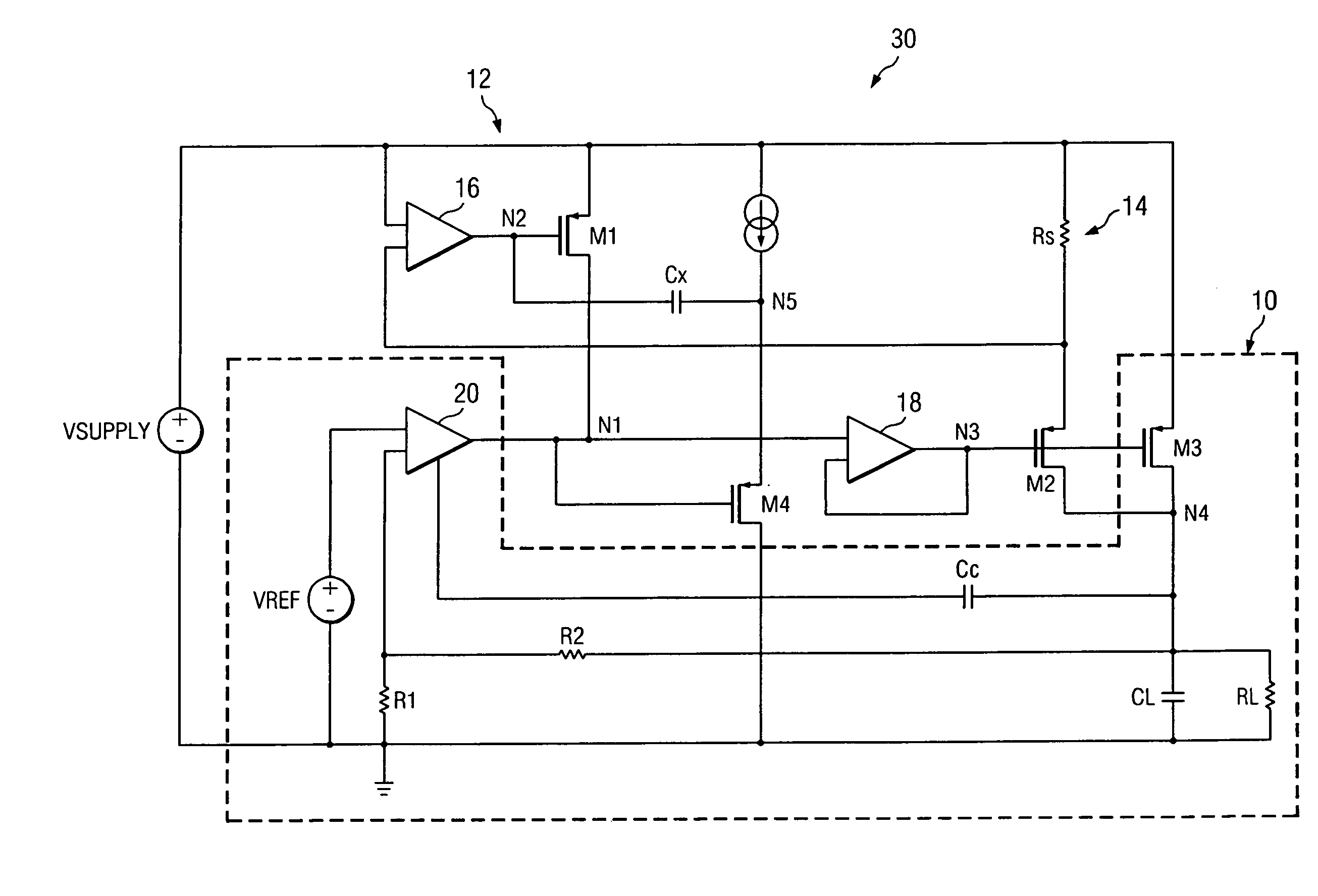
[0023]In general, the invention provides methods and circuits for decoupling the stability characteristics of loops within a circuit. Referring now primarily to FIG. 3, an overview of the methods and circuits of the invention is shown by this example of a schematic diagram of a circuit 30 wherein the stability characteristics of an LDO loop 10 and current limit loop 12 have been decoupled. Transistor M4 is shown coupled between the opamp 20 and buffer 18. The gate is connected to the output of the error amplifier 20, the drain is connected to ground, and the source is connected to node N5. At node N5, a current source is coupled to a power supply and the compensation capacitor Cx of the comparator 16.

[0024]Although a specific example of the invention is shown used in an LDO implementation with MOSFET transistors, it should be understood by those skilled in the arts that the invention may be employed in various current loops and using various alternative transistor types, for example...


PUM


Abstract

Circuits and methods for dynamically stabilizing a circuit having a relatively small capacitive load two current loop sub circuits are provided. A main current loop and an associated sensing loop are coupled such that a compensation capacitance supplied to each sub circuit loop individually will remain isolated and will not be cumulative with respect to the remainder of the circuit.

Description

TECHNICAL FIELD[0001]The invention relates to electronic circuits. More particularly, it relates to methods and circuits for stabilizing two associated current loops within an electronic circuit.BACKGROUND OF THE INVENTION[0002]Many electronic circuit applications require maintaining the stability of more than one sub circuit loop within a larger circuit. Challenges can arise, however, when the loop stability requirements come into conflict. For example, in some applications it is desirable to use low dropout regulators (LDOs) that have high stability at very low capacitive loads. This is attractive for reducing the cost associated with using additional external components. Also, portable applications require low dropout voltages and very low power consumption in order to accommodate battery-power limitations. A representative example of a low dropout regulator, in this case a PMOS LDO 10 known in the arts is shown in FIG. 1. A common approach to meeting these often conflicting desi...

Claims


Application Information

Patent Timeline
Patent Type & Authority Patents(United States)
IPC IPC(8): G05F1/10G05F3/02G05F3/16H03F1/08H03F1/56H03F3/347H03F3/45
CPCH03F1/08H03F1/56H03F3/347H03F3/45183H03F2200/153H03F2203/45248H03F2203/45264
Inventor PEREZ, RAUL ALEJANDRO
Owner TEXAS INSTR INC
Why Eureka
Try Eureka