Spatial focal field type glasses display

a display device and focal field technology, applied in the field of glasses display, can solve the problems of limited angle range, complex structure, and inability to display virtual images at different distances simultaneously, and achieve the effect of reducing the axial size of the display device and good immersive visual experien

Active Publication Date: 2016-11-29
BEIJING ANTVR TECH
View PDF13 Cites 8 Cited by
  • Summary
  • Abstract
  • Description
  • Claims
  • Application Information

AI Technical Summary

Benefits of technology

[0021]Preferably, a scene image is divided into a matrix consisting of a plurality of sub-images obtained from different view angles by the spatial focal field type glasses display, each of the sub-images are projected by a plurality of projection units (2) into human eyes, retina images of the sub-images formed on the retina after passing through the crystalline lens overlap with each other, the plurality of the sub-images from the different view angles are arranged so that when the focal length of the crystalline lens of the human eyes change to make the eyes be in different view states, the plurality of retina images of the sub-images from different view angles will overlap on the retina in same center of circles but with different radiuses which vary in a certain scale factor according to the different view states, so that a depth of field effect is generated where distant objects will be blur when the eyes focus on nearby objects and nearby objects will be blur when the eyes focus on distant objects.
[0023]1) It is better to simulate the focused and defocused mechanism to object light beams from different distances of the human eyes, which makes the display present virtual images at different distances simultaneously. The part that can be see clearly will be determined by the diopter of the crystalline lens actively controlled by the human eyes, without any need for additional optical or mechanical components to control the display distance separately.
[0024]2) A projection component which is combined with multiple projection units is adopted, which effectively reduces the axial size of the display device along the sight line. It is easy to manufacture a frame type glasses display with lighter and thinner lens, which can be used to produce cornea contact lens display when the size is small enough.
[0025]3) A projection component which is combined with multiple projection units is adopted, which can be used to produce a glasses display with big visual angle, even reaching the limit of the human eye visual angle, around 120°, with a good immersive visual experience.
[0026]4) No matter whether direct, light-source reflective or mirror reflective type is used, it is easy to produce a transmissive type glasses display according to the corresponding solution. The virtual images can be integrated into the real environment with a right display distance matching the real environment. The advantages of the spatial focal field type glasses display can be utilized well.

Problems solved by technology

The images displayed by the glasses display products available in the market are all in the same virtual image plane, so the function of displaying virtual images at different distances simultaneously cannot be achieved.
However, this solution needs to adopt lens of which curvature can be controlled by voltage, so the structure is complicated, and still not really realize that the virtual images can be displayed at different distances simultaneously.
The largest view angle of the human eyes is around 120°, but the angle range displayed by the existing glasses display is limited by its optical structure, and it is usually only around 50°.
Therefore, the experience on immersive visual is poor.

Method used


Image

  • Spatial focal field type glasses display
  • Spatial focal field type glasses display
  • Spatial focal field type glasses display

Examples


Embodiment Construction

[0050]With reference to the following exemplary embodiments and the accompanying drawings, the technical solutions of the present invention will be further explained:

[0051]The exemplary embodiments:

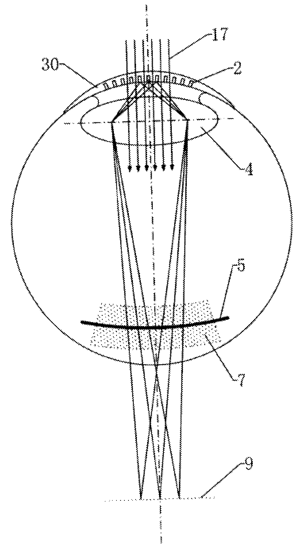
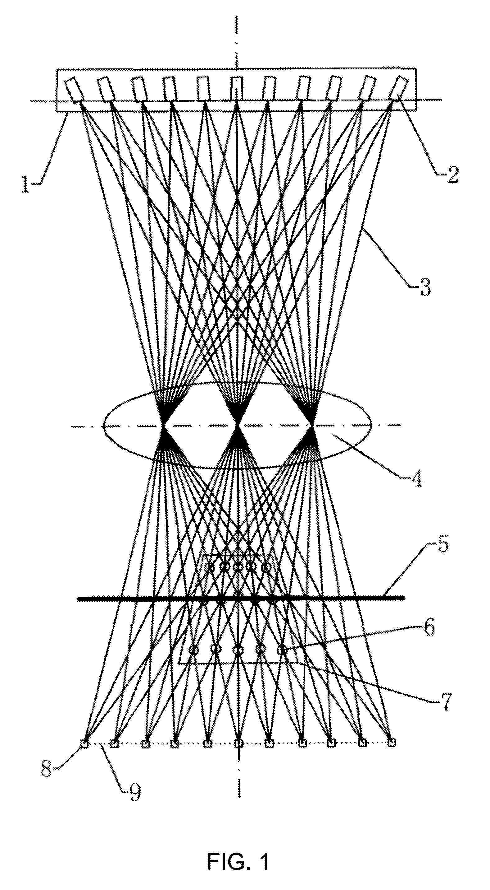
[0052]The display principle is as shown in FIG. 1. A spatial focal field type glasses display comprises a projection component (1) and a display control device. The projection component (1) is located in the lens of the frame type glasses or corneal contact lens, which is placed in front of the human eyes. The projection component (1) comprises a plurality of projection units (2) that are arranged side by side (there is 11 units totally in FIG. 1, but the units can also be arranged extending along the vertical direction of the paper, not shown in the figure). A single projection unit (2) projects a plurality of elementary beams (3 beams in FIG. 1). The three elementary beams (3) focus on the actual focus (8) again after passing through the crystalline lens (4). The actual focuses (8) of d...


PUM

PropertyMeasurementUnit
Focal distanceaaaaaaaaaa
view angleaaaaaaaaaa

Abstract

A spatial focal field type glasses display product can present virtual images at different distances simultaneously. The product is a frame type glasses or corneal contact lens and comprises a projection component and a display control device. The projection component comprises a plurality of projection units, each projection unit projects a plurality of elementary beams. The elementary beams projected by the same projection unit diverge and do not intercept with each other. The elementary beams projected by different projection units intersect near the retina after passing through the crystalline lens. The intersection point is a cluster focus. All cluster focuses form a spatial focal field which envelop the retina. When the diopter of the crystalline lens changes, the spatial focal field displaces and deforms accordingly, so different cluster focuses fall on the retina to be seen clearly, while the other cluster focuses tend to disperse and cannot be seen clearly.

Description

CROSS REFERENCE TO RELATED APPLICATIONS[0001]This is a continuation application of PCT Application No. PCT / CN2012 / 001415, titled “Three-dimensional Focal Field Spectacles Display,” filed Oct. 23, 2012, which is based upon and claims the benefit of priority from Chinese Application No. 201210119666.X, titled “Small Hole Projection Type Near-eye Display,” filed on Apr. 23, 2012. The entire contents of the above-referenced applications are incorporated herein by reference.TECHNICAL FIELD[0002]The present invention relates to a glasses display which is also known as the head mounted display (HMD) or near-eye display, especially relates to a glasses display which can present virtual images at different distances simultaneously.BACKGROUND OF THE INVENTION[0003]Focal distance of human eyes is from 10 cm to infinity, so the human eyes cannot see any objects within a distance of 10 cm. In order for the human eyes to clearly see the contents displayed by the display device which is very close...

Claims


Application Information

Patent Timeline
Patent Type & Authority Patents(United States)
IPC IPC(8): G02F1/1335G02C11/00G02B27/22G02B5/30G02B27/01G02C7/04
CPCG02C11/10G02B5/30G02B27/017G02B27/0172G02B27/2214G02F1/133528G02B2027/0118G02B2027/0127G02B2027/0134G02B2027/0178G02C7/04G02B30/27
Inventor QIN, ZHENG
Owner BEIJING ANTVR TECH
Why Eureka
Try Eureka