

Method and apparatus for manufacturing a battery safety valve, a battery safety valve, and method for manufacturing a battery case lid
a battery safety valve and manufacturing method technology, applied in the manufacture of cell components, final product manufacturing, vent arrangements, etc., can solve the problems of reducing the lifespan affecting the production efficiency of the die assembly, so as to reduce the amount of processing applied to the metal sheet by a reduce the working load on the single annular projecting portion, and suppress the occurrence of work hardening
- Summary
- Abstract
- Description
- Claims
- Application Information
AI Technical Summary
Benefits of technology
Problems solved by technology
Method used
Image

Examples
first embodiment
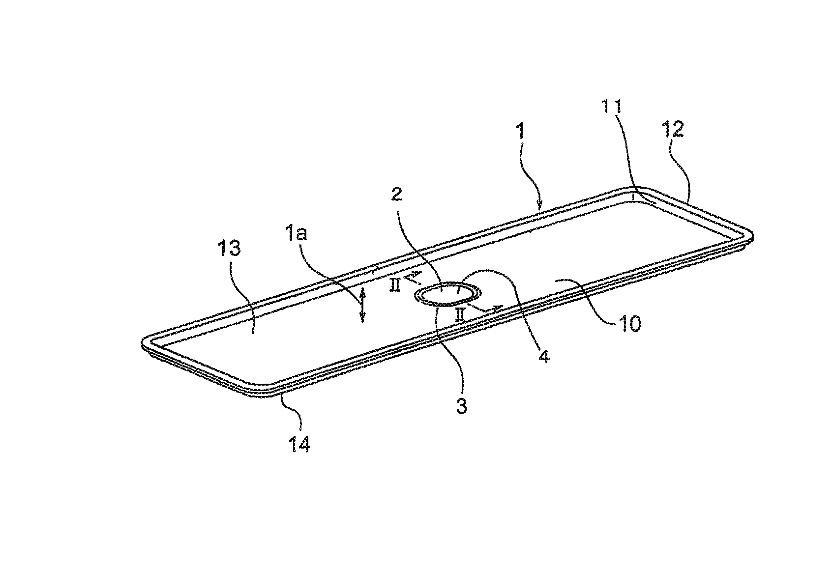
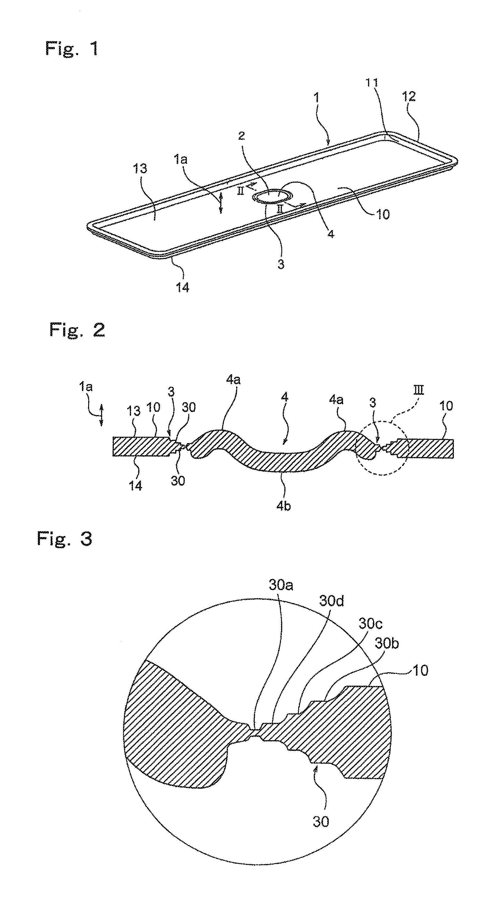
[0027]FIG. 1 is a perspective view showing a safety valve 2 of a secondary battery according to a first embodiment of the present invention. In the drawing, a lid 1 is constituted by a stainless steel metal sheet, and constitutes a battery case of the secondary battery. The lid 1 is provided with the safety valve 2 for a secondary battery, which ruptures when an internal pressure of the battery case exceeds a predetermined value so as to release the internal pressure to the outside. The safety valve 2 is provided with a thin annular portion 3 and a bent portion 4.
[0028]The thin annular portion 3 is an elliptical groove constituting an edge portion of the safety valve 2, and is formed to be thinner than the remaining sheet surface of the lid 1. The thin annular portion 3 splits first when the internal pressure of the battery case exceeds a predetermined value, thereby causing the entire safety valve 2 to rupture. Note that an outer shape of the thin annular portion 3 may take any for...
second embodiment
[0053]FIG. 5 is a perspective view showing a lid 1 of a battery case according to a second embodiment of the present invention. In the drawing, the lid 1 constituting the battery case of a secondary battery is provided with a safety valve 2 for a secondary battery, which ruptures when an internal pressure of the battery case exceeds a predetermined value so as to release the internal pressure to the outside. The safety valve 2 is provided with a thin annular portion 3 and a bent portion 4.
[0054]The thin annular portion 3 is an elliptical groove constituting an edge portion of the safety valve 2, and is formed to be thinner than the remaining sheet surface of the lid 1. The thin annular portion 3 splits first when the internal pressure of the battery case exceeds a predetermined value, thereby causing the entire safety valve 2 to rupture. Note that an outer shape of the thin annular portion 3 may take any form having an enclosed outer edge, for example a circular form, a polygonal fo...
third embodiment
[0087]FIG. 10 is an illustrative view showing a method for manufacturing a battery case lid according to a third embodiment of the present invention. In the second embodiment, tensile stress acting on the thin annular portion 3 during the drawing process is reduced by implementing the drawing process on the metal sheet 100 in a condition where the outer peripheral side sheet surface 10 on the periphery of the thin annular portion 3 is restrained by the restraining means 54. It is however difficult to eliminate the action of the tensile stress on the thin annular portion 3 completely, and therefore the thickness of the thin annular portion 3 may be reduced by tensile stress. When the thickness of the thin annular portion 3 decreases below a predetermined thickness, the thin annular portion 3 ruptures before the internal pressure of the battery case reaches a pre-envisaged pressure.
[0088]Hence, whereas in the second embodiment the thickness of the thin annular portion 3 is reduced to ...
PUM
| Property | Measurement | Unit |
|---|---|---|
| thickness | aaaaa | aaaaa |
| thickness | aaaaa | aaaaa |
| thickness | aaaaa | aaaaa |
Abstract
Description
Claims
Application Information