Method for producing optical beam splitter cubes

a technology of optical beam splitter and cube, which is applied in the direction of glass separating apparatus, glass making apparatus, instruments, etc., can solve the problems of high production cost, complex production and thus high production cost, and is not possible until now to use the splitter cube in very cost-sensitive application cases, so as to achieve more cost-effective production and cost-sensitive

Active Publication Date: 2016-12-06
SCHILDTEC
View PDF6 Cites 3 Cited by
  • Summary
  • Abstract
  • Description
  • Claims
  • Application Information

AI Technical Summary

Benefits of technology

[0008]It is an object of the invention to specify a method for producing optical beam splitter cubes which allows a substantially more cost-effective production of these beam splitter cubes compared with the production method until now, and thus also opens up the use thereof to substantially more cost-sensitive applications compared with the possible uses until now.
[0024]The double prism plates are detachably glued to an adhesive support layer on a side with the ridge lines, projecting therein, of the prism bars. The prism bars arranged on the depositing side then (detachably) adhere to the adhesive support layer along their projecting ridge lines. If, in a subsequent production process, the double prism plates are now cut up along the valleys between the prism bars, the adhesive joints on the ridge lines of the prism bars guarantee that the position of the prism bars relative to each other does not change during the separation process, with the result that a quite precise implementation of the separation processes to be carried out is ensured.
[0029]The use of at least one holding web, running transverse to the prism bars, on each prism plate at the same height as the latter is not necessary, but brings the advantage, with regard to adhesion of the double prism plates on the support layer, that the contact not only takes place on the support layer along the relatively small ridge surfaces of the prism bars, but is significantly enlarged by the surface of each holding web then likewise adhesively resting on the adhesive support layer, whereby the fixing of the double prism plate to the adhesive support layer as a whole is significantly strengthened without the subsequent optical surfaces being contacted at this stage.
[0031]In a quite particularly advantageous embodiment of the method according to the invention, as adhesive support layer, an auxiliary support is used, to the top side of which facing the double prism plate a layer of adhesive, deformable material, e.g. wax, is attached, into which the projecting ridge lines of the prism bars of the underside of the double prism plate facing the adhesive support layer are pressed to construct a releasable adhesive joint. For the formation of the layer on the auxiliary support, any suitable adhesive that adheres well and produces a releasable adhesive joint can be used, wherein e.g. the use of “Spezial-Kittlack C15”® from Satisloh AG, Baar, Switzerland, has particularly proved its worth. If such a suitable adhesive is used as overlay on the auxiliary support, even a slight pressing of the ridge lines of the prism bars can lead to the production of an adhesive joint which is so strong that it also securely prevents not only a slipping, but also a tilting of the prism bars, even without holding web(s), during a separation process which is carried out at right angles to the longitudinal direction of the prism bars.
[0042]For the separation of the double prism plate along the longitudinal direction, thus for the production of the prism rods, it is advantageous if the separation process only has to take place through the plate. For this reason, it is advantageous to form the valley floor between neighboring prism bars such that the surface of the plate (or the coated surface of the plate) freely rests against it in a strip. In this area, the separation process can then take place without the need to sever material of the prism bars.
[0044]In order to prevent edges of the plate from protruding, after the isolation into beam splitters, on the boundary surfaces of the beam splitter, in a development of the variant with prism bars offset against each other and spaced apart by the plate thickness as well as additionally by the disconnecting cut width the severing cut can additionally be carried out at an angle of 45°. The boundary surfaces of the resulting beam splitter which, because of the section of the plate which lies between the prisms, is no longer cubic, but rather is square. This achieves that the boundary surfaces of this beam splitter have no projections.

Problems solved by technology

However, this production is elaborate and thus expensive, which, until now, has limited the use of such beam splitter cubes almost exclusively to application cases in which the relatively high production costs are still economically justifiable.
At the same time, it was not possible until now to use the splitter cubes in very cost-sensitive application cases because of their elaborate production method.

Method used


Image

  • Method for producing optical beam splitter cubes
  • Method for producing optical beam splitter cubes
  • Method for producing optical beam splitter cubes

Examples


Embodiment Construction

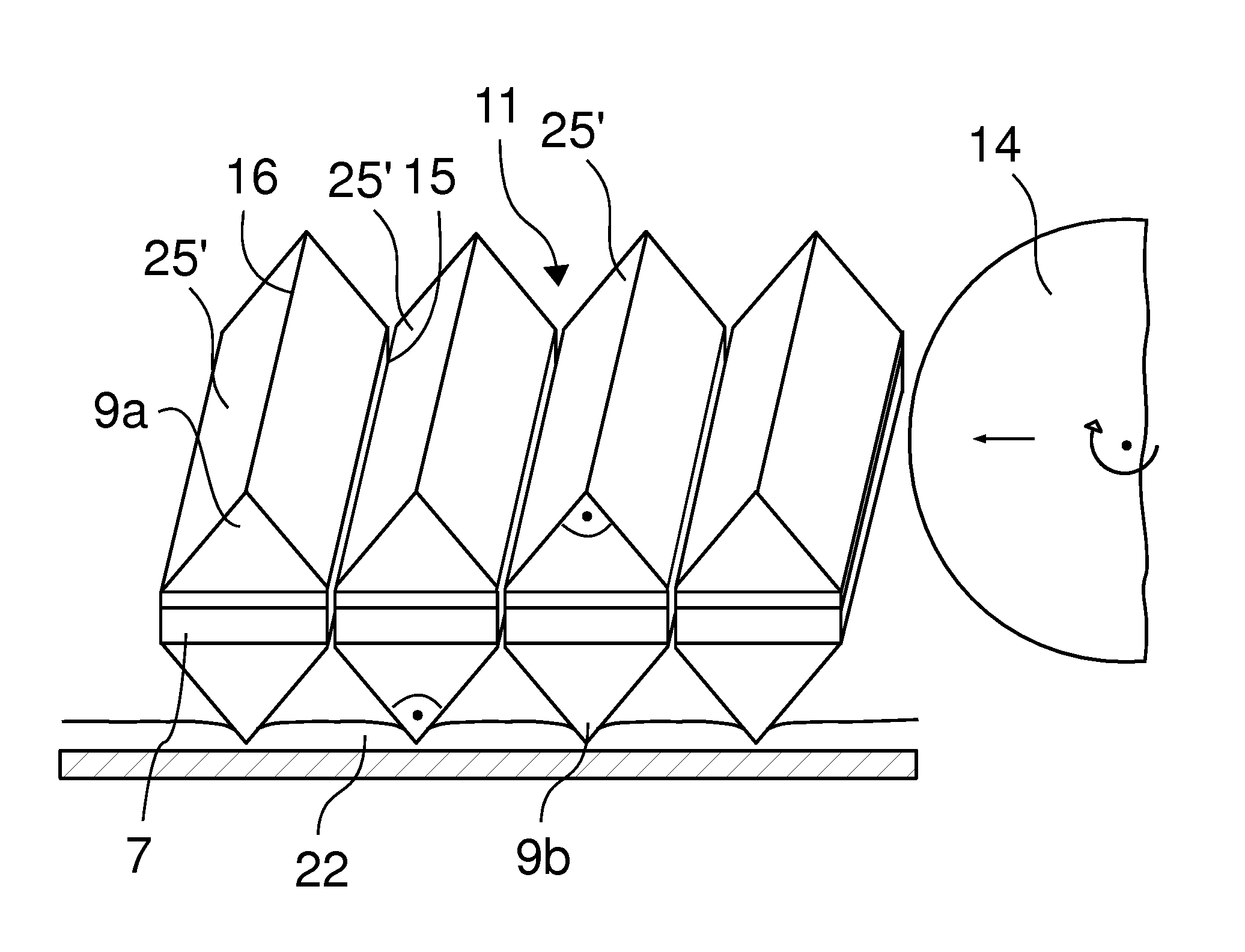
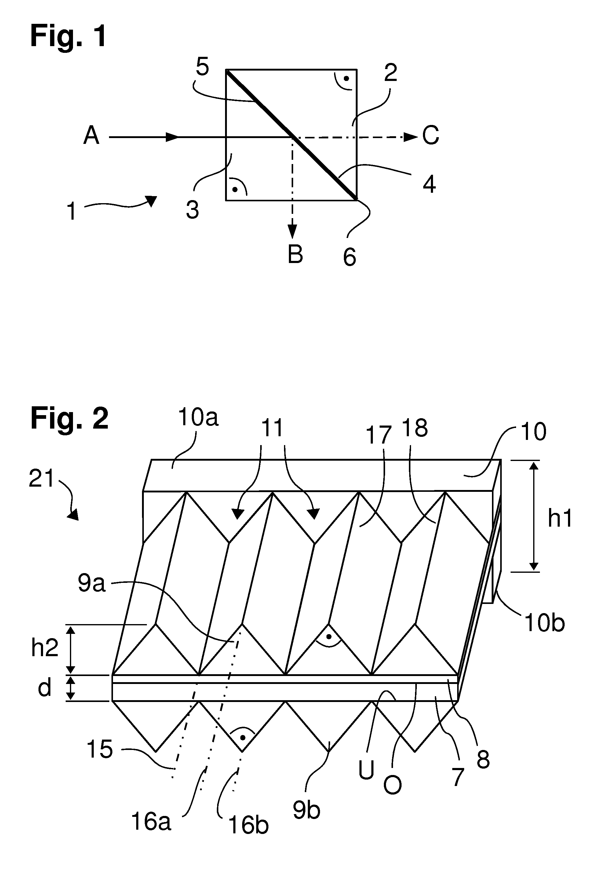
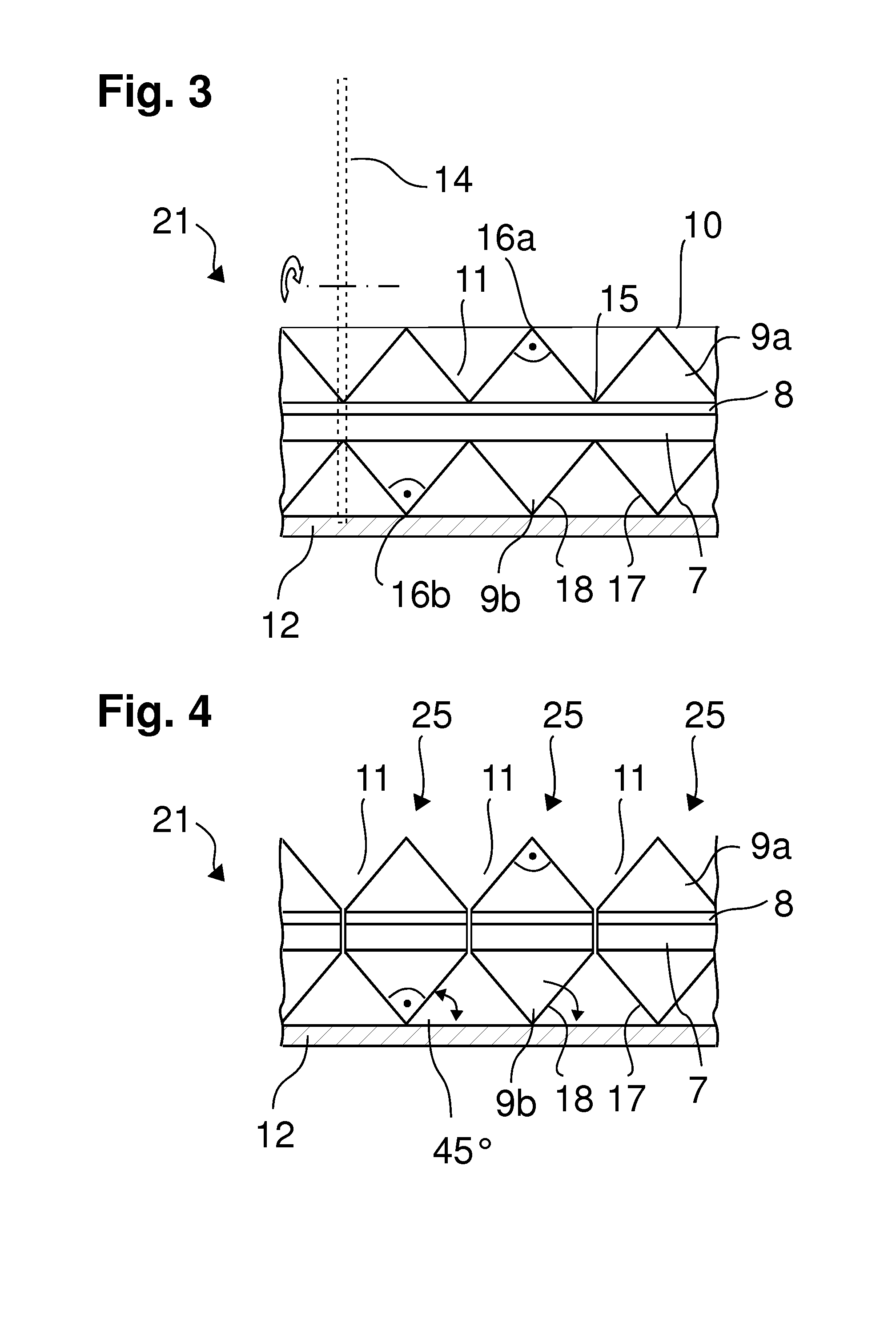
[0065]The representation of FIG. 1 shows a schematic, simplified side view of a beam splitter cube 1. This has two prisms 2, 3 which are right-angled triangles in cross section and which are laid with their base surfaces 4, 5 against each other and are cemented together by means of a cement layer.

[0066]In FIG. 1 a light beam A is also shown which is incident through an optical side face of the prism 3 into the beam splitter cube 1, wherein the base surfaces 4, 5, lying against each other, of the prisms 2, 3 lie at a 45° angle to the beam path of the incident beam A.

[0067]A portion of the light beam A is reflected at the joint plane, formed by the two base surfaces 4, 5, of the beam splitter cube 1 at an angle of 90° and emerges as a partial beam B on the other optical side face of the prism 3.

[0068]However, a portion of the entrance beam A passes through the beam splitter cube 1 and emerges from it again as partial beam C on its cube side opposite the entry side of the entrance beam...


PUM

PropertyMeasurementUnit
angleaaaaaaaaaa
tilt angleaaaaaaaaaa
angleaaaaaaaaaa

Abstract

To produce optical beam splitter cubes, an optically transparent plate is provided with an optically active layer on a cover side. Then, on both cover sides of the plate, a plurality of prism bars are formed by molding an optically transparent material, so that a double prism plate is obtained. The prism bars are arranged on cover sides of the plate projecting roof-like in ridge lines separated from each other by valleys. Each prism bar has the cross section of an isosceles right-angled triangle, complemented by the prism bar lying opposite on the other cover side of the plate to form the cross section of the beam splitter cube. The double prism plate is cut up along the valleys between the prism bars and transverse to the longitudinal direction into segments which in each case form a beam splitter cube.

Description

RELATED APPLICATIONS[0001]The present application is a National Phase entry of PCT Application No. PCT / EP2013 / 073250, filed Nov. 11, 2013, which claims priority from DE Patent Application No. 10 2012 221 011.3, filed Nov. 16, 2012, said applications being hereby incorporated by reference herein in their entirety.FIELD OF THE INVENTION[0002]The invention relates to a method for producing optical beam splitter cubes.BACKGROUND OF THE INVENTION[0003]Optical beam splitter cubes are optical components by means of which a light beam can be split into two partial beams or two radiation paths can be combined into a single beam. These can be beams with different polarizations and / or different wavelengths. A particular advantage is that the transmitted beam passes through the beam splitter cube without beam displacement or beam deflection.[0004]Until now, to produce beam splitter cubes, prisms were produced individually, optionally polished, coated and then two such prisms were cemented toget...

Claims


Application Information

Patent Timeline
Patent Type & Authority Patents(United States)
IPC IPC(8): G02B27/10C03B19/02C03B33/06C03C17/06
CPCG02B27/1073C03B19/02C03B33/06C03C17/06
Inventor FREITAG, HANS-JOACHIM
Owner SCHILDTEC
Why Eureka
Try Eureka