Fluorescence endoscope apparatus
a fluorescence endoscope and endoscope technology, applied in the direction of fluorescence/phosphorescence, instruments, catheters, etc., can solve the problem of difficult to find the position of lesions in which fluorescent dyes accumula
- Summary
- Abstract
- Description
- Claims
- Application Information
AI Technical Summary
Benefits of technology
Problems solved by technology
Method used
Image
Examples
first embodiment
An Example of the Substitution of 0
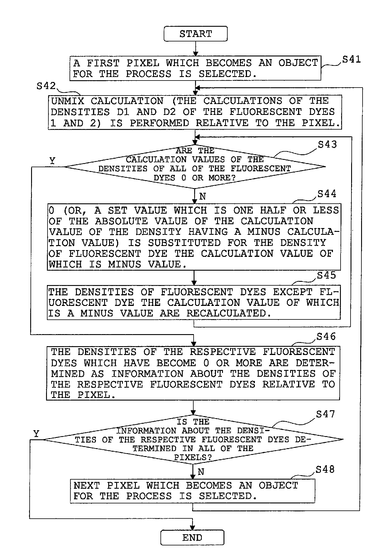
[0068]The fluorescence endoscope apparatus of the first embodiment is formed in such a way that, in the case of obtaining fluorescence images for three kinds of fluorescent dyes 1 to 3 at three wavelength values λ1 to λ3, when there exists a pixel in which at least one of the calculation values of the densities D1 to D3 of the fluorescent dyes 1 to 3 which are calculated with the matrix equation (1′) for finding the densities D1 to D3 of the fluorescent dyes 1 to 3 is smaller than 0, the fluorescent dye density-calculating unit 34 substitutes 0 for the density of fluorescent dye the calculation value of which is smaller than 0, in the equation (1′), and the fluorescent dye density-calculating unit 34 recalculates the densities of fluorescent dyes except fluorescent dye the calculation value of which is smaller than 0, relative to the pixel.
[0069]In the case where there exists a pixel in which the calculation value of the density D3 of the fluoresce...
second embodiment
An Example of the Substitution of a Number Different from 0
[0077]The fluorescence endoscope apparatus of the second embodiment is formed in such a way that, in the case of obtaining fluorescence images for three kinds of fluorescent dyes 1 to 3 at three wavelength values λ1 to λ3, when there exists a pixel in which at least one of the calculation values of the densities D1 to D3 of the fluorescent dyes 1 to 3 which are calculated with the matrix equation (1′) for finding the densities D1 to D3 of the fluorescent dyes 1 to 3 is smaller than 0, the fluorescent dye density-calculating unit 34 substitutes a number different from 0 for the density of a fluorescent dye the calculation value of which is smaller than 0, in the equation (1′), and the fluorescent dye density-calculating unit 34 recalculates the densities of fluorescent dyes except fluorescent dye the calculation value of which is smaller than 0, relative to the pixel.
[0078]Values which the fluorescent dye density-calculating ...
third embodiment
An Example of the Substitution of the Calculation Value of the Density of a Fluorescent Dye in a Set Pixel that is Located in the Vicinity of a Pixel in which the Fluorescent Dye has a Calculation Value Smaller than 0
[0081]The fluorescence endoscope apparatus of the third embodiment is formed in such a way that, in the case of obtaining fluorescence images for three kinds of fluorescent dyes 1 to 3 at three wavelength values λ1 to λ3, when there exists a pixel in which at least one of the densities D1 to D3 of the fluorescent dyes 1 to 3 which are calculated with the matrix equation (1′) for finding the densities D1 to D3 of the fluorescent dyes 1 to 3 is smaller than 0, the fluorescent dye density-calculating unit 34 substitutes for the density of fluorescent dye the calculation value of which is smaller than 0 the calculation value of density which the corresponding fluorescent dye the calculation value of which is smaller than 0 in the pixel has in a set pixel that is located in ...
PUM
| Property | Measurement | Unit |
|---|---|---|
| wavelength | aaaaa | aaaaa |
| wavelength | aaaaa | aaaaa |
| wave length | aaaaa | aaaaa |
Abstract
Description
Claims
Application Information
 - R&D
- Intellectual Property
- Life Sciences
- Materials
- Tech Scout
- Unparalleled Data Quality
- Higher Quality Content
- 60% Fewer Hallucinations
Browse by: Latest US Patents, China's latest patents, Technical Efficacy Thesaurus, Application Domain, Technology Topic, Popular Technical Reports.
© 2025 PatSnap. All rights reserved.Legal|Privacy policy|Modern Slavery Act Transparency Statement|Sitemap|About US| Contact US: help@patsnap.com


