
Device and method for determining carbon dioxide content of air

Inactive Publication Date: 2016-12-20
SIEMENS AG
View PDF16 Cites 9 Cited by
  • Summary
  • Abstract
  • Description
  • Claims
  • Application Information

AI Technical Summary

Benefits of technology

The patent is for a gas sensor that also heats up when the gas value is corrected, which helps stabilize the baseline signal. The sensor is designed with a gas-sensitive layer and a polymer, which reduces the impact of air humidity on the carbon dioxide measurement. This allows for accurate readings even at room temperature. The sensor can be read using a GasFET, which improves sensitivity and eliminates the need for a reference humidity.

Problems solved by technology

It is problematic in such cases that the carbon dioxide molecule is a linear, symmetrical molecule and therefore no electrical dipole moment is present, which with various transducer principles can give rise to a sensor signal.
Furthermore the molecule is chemically very unreactive.
The disadvantage of optical spectroscopy is however the complex structure of the measurement systems and the significant outlay necessary for evaluating the measured spectra.
This ultimately leads to comparatively large and expensive measurement systems.
However the disadvantage of solid-state sensors is that they are dependent on a certain reactivity of the molecules to be measured and simultaneously however detect all molecules which just have a certain reactivity.
Above all this makes the measurement of less reactive species such as carbon dioxide difficult with such sensors, since they mostly react very strongly to hydrocarbons or ozone.
The number of potential interference gases is substantial in such cases.
Road traffic and even the weather conditions also lead to the occurrence of gases.
The disadvantage of the known sensors is that a further sensor is necessary to determine and compensate for air humidity.

Method used


Image

  • Device and method for determining carbon dioxide content of air
  • Device and method for determining carbon dioxide content of air
  • Device and method for determining carbon dioxide content of air

Examples


Embodiment Construction

[0047]Reference will now be made in detail to the preferred embodiments, examples of which are illustrated in the accompanying drawings, wherein like reference numerals refer to like elements throughout.

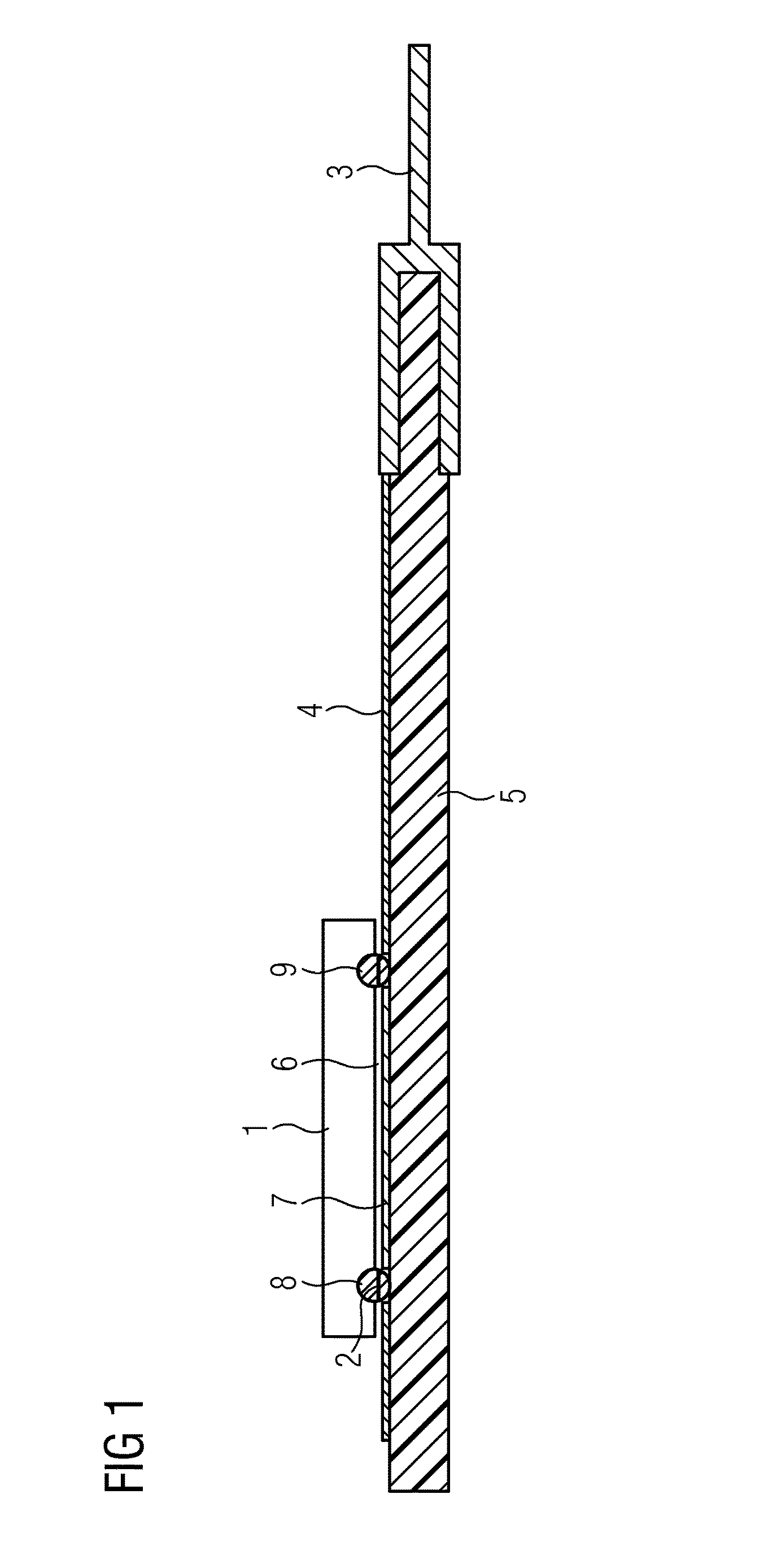
[0048]FIG. 1 shows the basic structure of a gas-sensitive FET in accordance with an example of a structure. Illustrated in FIG. 1 is a CMOS transistor 1 with a source electrode 8 and a drain electrode 9. In this case a FET structure in the form of the CMOS transistor 1 is mounted in flip-chip technology on a ceramic substrate 5 provided with conductor tracks 4. This can be done for example by a conductive adhesive 2. The gas-sensitive layer 7 is partly applied to the ceramic substrate 5 and is contacted accordingly with the conductor tracks 4. The gas channel is the air gap 6 between gate and CMOS transistor. The ceramic substrate 5 serves as a carrier of the gas-sensitive layer and simultaneously as a carrier of the entire sensor structure, so that in this example no building into a...


PUM


Abstract

A gas sensor, for example for use in air conditioning systems, has a gas-sensitive layer that includes a material that is sensitive to carbon dioxide. The material has a cross-sensitivity to air humidity. This is compensated for by measurement at two different temperatures. The measured gas values are calculated together, with the assumption that the sensitivity of the gas sensor to carbon dioxide exhibits a different curve with the temperature of the gas sensor than the sensitivity to water.

Description

CROSS REFERENCE TO RELATED APPLICATIONS[0001]This application is the U.S. national stage of International Application No. PCT / EP2012 / 060001, filed May 29, 2012 and claims the benefit thereof. The International Application claims the benefit of German Application No. 102011077559.5 filed on Jun. 15, 2011, both applications are incorporated by reference herein in their entirety.BACKGROUND[0002]Described below are a carbon dioxide sensor for determining the carbon dioxide content of air and a method for creating a measured gas value which represents the carbon dioxide concentration in air.[0003]The detection of carbon dioxide is of great interest for a number of applications. Examples are the assessment of air quality in internal spaces, energy-efficient control of air conditioning systems or checking cleaned air. The aim of carbon dioxide detection can be to enhance comfort. It is however also possible to achieve significant energy savings under some circumstances.[0004]Thus, for exam...

Claims


Application Information

Patent Timeline
IPC IPC(8): G01N27/414G01N33/00
CPCG01N33/004G01N27/4143
Inventor FLEISCHER, MAXIMILLIANPOHLE, ROLANDSTEGMEIER, STEFANVON SICARD, OLIVER
Owner SIEMENS AG
Learn More