Pivot mechanism of synchronous hinge device

a technology of synchronous transmission and pivot mechanism, which is applied in the direction of hinges, casings/cabinets/drawer details, instruments, etc., can solve the problems of affecting the stability of synchronous transmission, lowering the possibility of shortening the distance between the axes of two parallel shafts, and affecting the transmission stability, so as to achieve stably transmit power, shorten the distance between the two shafts, and high contact ratio

Active Publication Date: 2016-12-20
FIRST DOME
View PDF13 Cites 21 Cited by
  • Summary
  • Abstract
  • Description
  • Claims
  • Application Information

AI Technical Summary

Benefits of technology

[0009]It is therefore a primary object of the present invention to provide a pivot mechanism of the synchronous hinge device, which is applied to a foldable electronic apparatus. The pivot mechanism can shorten the distance between two shafts of the dual-shaft hinge and stably transmit power by high contact ratio, whereby the electronic device can have a miniaturized and lightweight structure and can be smoothly rotated. The pivot mechanism includes a driver disposed on a first shaft and a reactor disposed on a second shaft and a link unit. Spur gears and conical (bevel) gears are respectively disposed at two ends of the link unit and the driver and the reactor. The Spur gears and conical (bevel) gears are engaged with each other to transmit power. The spur gears and conical (bevel) gears can be smoothly engaged with each other to form a stable, miniaturized and lightweight synchronous transmission device to overcome the shortcomings of the conventional device. When the first shaft drives the driver to rotate, the driver drives the link unit to rotate. At this time, the reactor is driven by the link unit to rotate in a direction reverse to the rotational direction of the driver. Accordingly, the first and second shafts can be synchronously rotated in reverse directions.
[0010]In the above pivot mechanism of the synchronous hinge device, the synchronous transmission device is disposed between a main fixing plate and a subsidiary fixing plate. The link unit is pivotally disposed between the base sections of the main fixing plate and the subsidiary fixing plate. The base sections are formed with grooves for lowering the frictional force against the link unit. A lubricant or the like can be filled in the grooves to keep the link unit more smoothly rotated between the base sections.

Problems solved by technology

However, it is still necessary to keep a full gap between the engaged teeth for smoothening the operation.
This will lead to greater error in transmission.
This not only affects the stability of the synchronous transmission between the transmission gears, but also lowers the possibility of shortening of the distance between the axes of the two parallel shafts.
As a result, the miniaturization of the volume and thickness of the dual-shaft hinge is greatly limited.
This obviously is unbeneficial to the requirement of lightweight and thinning of the entire electronic apparatus.
Therefore, a gap may exist between the guide threaded rods and the slide block.
In the synchronous mechanism, such gap often leads to shake and displacement of the rotary shafts.
As a result, the rotary shafts can be hardly stably operated.
When the electronic apparatus is folded open and used by any angle, the locating effect and the stability of use of the electronic apparatus may be affected.
Moreover, the two opposite guide threaded rods necessitate longer operation travel.
This is unbeneficial to the miniaturization of the dual-shaft torque hinge.
In the above dual-shaft hinge, in the case that the middle conical gears are disposed between the lateral sides of the parallel rotary shafts for transmitting the power, due to the cone distance or the face distance, it will be impossible to minimize the distance between the two rotary shafts.
Especially, the transmission mechanism applied to the notebook or a mini-type electronic apparatus fails to meet the requirements of lightweight and thinning of the electronic apparatus.
However, due to the gaps between the teeth and the slide member, the synchrony and stability of operation of the two parallel rotary shafts will be both ill affected.
However, such transmission mechanism is disadvantageous in that the volume of the electronic apparatus will be increased and more room is occupied.

Method used


Image

  • Pivot mechanism of synchronous hinge device
  • Pivot mechanism of synchronous hinge device
  • Pivot mechanism of synchronous hinge device

Examples


Embodiment Construction

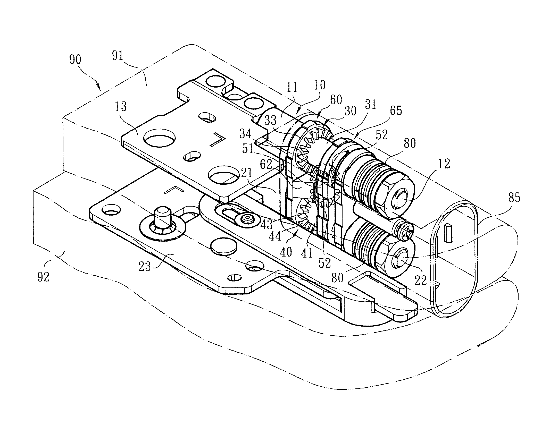
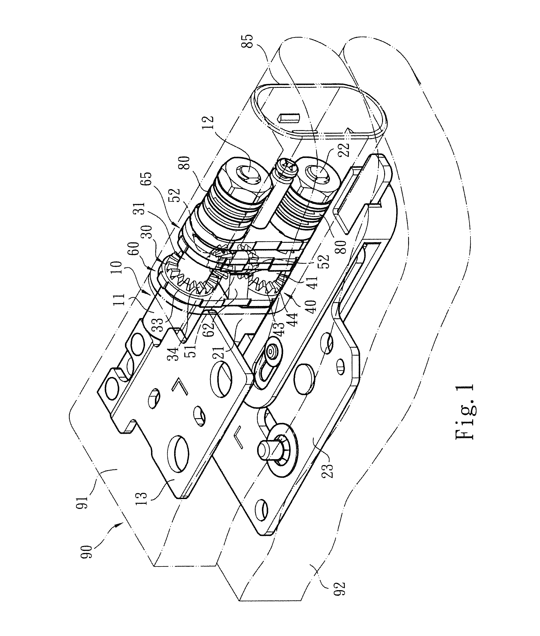
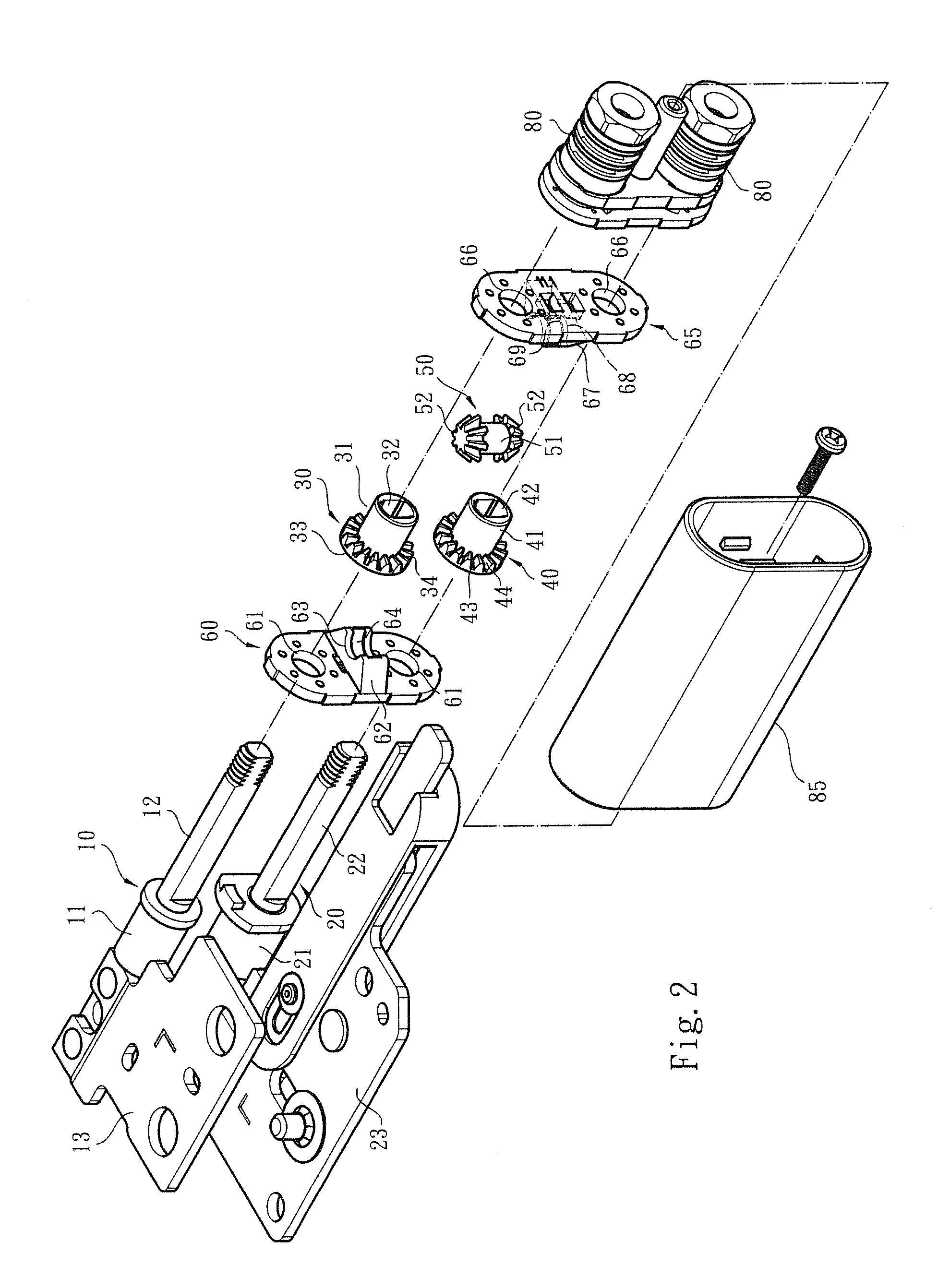
[0017]Please refer to FIGS. 1, 2 and 3. The pivot mechanism of synchronous hinge device of the present invention includes a first shaft 10 and a second shaft 20. Each of the first and second shafts 10, 20 has a fixed section 11, 21 and a pivoted section 12, 22. The fixed sections 11, 21 are assembled with fixing seats 13, 23 to respectively fix the first and second shafts 10, 20 on a display module 91 and an apparatus body module 92 of an electronic apparatus 90 (such as a mobile phone, a computer or the like). The pivoted sections 12, 22 of the first and second shafts 10, 20 are respectively assembled with torque modules 80. Accordingly, when the action force applied to the display module 91 and the apparatus body module 92 by a user for rotating the same disappears, the display module 91 and the apparatus body module 92 are immediately located.

[0018]As shown in FIGS. 1, 2 and 3, a synchronous transmission device is disposed on the pivoted sections 12, 22 of the first and second sh...


PUM


Abstract

A pivot mechanism of the synchronous hinge device is applied to a foldable electronic apparatus. The pivot mechanism can be stably rotated and the distance between two shafts of the dual-shaft hinge is shortened, whereby the electronic device can be smoothly rotated and have a miniaturized and lightweight structure. The pivot mechanism includes a driver disposed on a first shaft and a reactor disposed on a second shaft and a link unit. Spur gears and conical (bevel) gears are respectively disposed at two ends of the link unit and the driver and the reactor. The Spur gears and conical (bevel) gears are engaged with each other to transmit power, whereby the first shaft with the driver and the second shaft with the reactor can be stably synchronously rotated in reverse directions.

Description

BACKGROUND OF THE INVENTION[0001]1. Field of the Invention[0002]The present invention relates to a pivot mechanism of synchronous hinge device.[0003]2. Description of the Related Art[0004]Along with the development of electronic apparatuses, various hinge devices have been developed and applied to panel products. By means of the hinge device, an electronic product composed of two foldable parts can be relatively 360-degree folded back onto itself. The electronic product can be smoothly rotated to a 360-degree fully opened position or rotated to a 0-degree fully closed position or rotated to any angular position therebetween and kept partially opened. Many kinds of synchronous or asynchronous hinge mechanisms have been developed and applied to the electronic products. A conventional synchronous hinge device includes multiple gears engaged with each other to synchronously open / close the two foldable parts of the electronic apparatus.[0005]In order to conveniently carry and use the fol...

Claims


Application Information

Patent Timeline
Patent Type & Authority Patents(United States)
IPC IPC(8): E05D3/06H05K5/02G06F1/16
CPCG06F1/16G06F1/1681
Inventor HSU, AN SZULEE, WANG JUILIN, CHUNG YILIN, YA CHING
Owner FIRST DOME
Why Eureka
Try Eureka